
Manual
e3
DS30757 Rev. 5 - 2 1 of 3 SBL30L30CT
www.diodes.com
ã Diodes Incorporated
SBL30L30CT
30A DUAL LOW VF SCHOTTKY BARRIER RECTIFIER
Features
Single phase, half wave, 60Hz, resistive or inductive load.
For capacitive load, derate current by 20%.
·
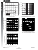
Case: TO-220AB
·
Case Material: Molded Plastic. UL Flammability
Classification Rating 94V-0
·
Moisture Sensitivity: Level 1 per J-STD-020C
·
Terminals: Tin Finish. Solderable per MIL-STD-202,
Method 208
·
Polarity: See Diagram
·
Marking: Type Number
·
Ordering Information: See Sheet 3
·
Weight: 2.24 grams (approximate)
Mechanical Data
L
M
A
N
P
D
E
K
C
B
G
12 3
J
HH
Pin 1
Pin 3
Pin 2
Case
Characteristic Symbol
Value
Unit
Peak Repetitive Reverse Voltage
Working Peak Reverse Voltage
DC Blocking Voltage
V
RRM
V
RWM
V
R
30 V
RMS Reverse Voltage
V
R(RMS)
21 V
Average Rectified Output Current @ T
C
= 140°C Total Device
Per Element
I
O
30
15
A
Non-Repetitive Peak Forward Surge Current
8.3ms Single half sine-wave Superimposed on Rated Load
Per Element
I
FSM
260 A
Peak Repetitive Reverse Current Per Element at t
P
= 2ms, 1 KHz
I
RRM
1.0 A
Voltage Rate of Change
dV/dt 10,000 V/ms
Typical Thermal Resistance Junction to Case Per Diode
(Note 2) Total
R
qJC
1.5
0.8
°C/W
Operating Temperature Range
T
j
-65 to +150 °C
Storage Temperature Range
T
STG
-65 to +150 °C
Notes: 1. RoHS revision 13.2.2003. Glass and High Temperature Solder Exemptions Applied, see
EU Directive Annex, Notes 5 and 7.
2. Thermal Resistance Junction to Case: Device mounted on 200x200x5mm aluminum plate.
3. Short duration test pulse used to minimize self-heating effect.
·
Low Power Loss, High Efficiency
·
Guard Ring for Transient Protection
·
High Surge Capability
·
Very Low Forward Voltage Drop
·
For Use in High Frequency Inverters, Free Wheeling, and
Polarity Protection Applications
·
Lead Free Finish, RoHS Compliant (Note 1)
NEW PRODUCT
Maximum Ratings
@ T
A
= 25°C unless otherwise specified
Electrical Characteristics
@ T
A
= 25°C unless otherwise specified
Characteristic Symbol
Min Typ Max Unit
Test Condition
Reverse Breakdown Voltage (Note 3)
V
(BR)R
30 ¾¾V
I
R
= 1.5mA
Forward Voltage Per Element
V
F
¾
¾
¾
¾
¾
¾
0.52
¾
0.46
0.38
0.57
0.50
V
@ I
F
= 15A, T
j
= 25°C
@ I
F
= 15A, T
j
= 125°C
@ I
F
= 30A, T
j
= 25°C
@ I
F
= 30A, T
j
= 125°C
Peak Reverse Current Per Element (Note 3)
I
R
¾
¾
¾
¾
1.0
300
mA
mA
@ V
R
= 30V, T
j
= 25°C
@ V
R
= 30V, T
j
= 125°C
TO-220AB
Dim Min Max
A
14.22 15.88
B
9.65 10.67
C
2.54 3.43
D
5.84 6.86
E
¾ 6.35
G
12.70 14.73
H
2.29 2.79
J
0.51 1.14
K
3.53Æ 4.09Æ
L
3.56 4.83
M
1.14 1.40
N
0.30 0.64
P
2.03 2.92
All Dimensions in mm