
User guide

SBR1A40S3
Document number: DS31528 Rev. 2 - 2
2 of 4
www.diodes.com
November 2010
© Diodes Incorporated
SBR1A40S3
SBR is a registered trademark of Diodes Incorporated.
Maximum Ratings @T
A
= 25°C unless otherwise specified
Single phase, half wave, 60Hz, resistive or inductive load.
For capacitance load, derate current by 20%.
Characteristic Symbol Value Unit
Peak Repetitive Reverse Voltage
Working Peak Reverse Voltage
DC Blocking Voltage
V
RRM
V
RWM
V
RM
40 V
RMS Reverse Voltage
V
R
(
RMS
)
28 V
Average Rectified Output Current T
C
= 65°C I
O
1 A
Non-Repetitive Peak Forward Surge Current
8.3ms Single Half Sine-Wave Superimposed on Rated Load
I
FSM
20 A
Thermal Characteristics
Characteristic Symbol Value Unit
Maximum Thermal Resistance
Thermal Resistance Junction to Ambient (Note 4)
Thermal Resistance Junction to Ambient (Note 5)
R
θ
JA
R
θ
JA
473
407
ºC/W
Operating and Storage Temperature Range
T
J
, T
STG
-65 to +150 ºC
Electrical Characteristics @T
A
= 25°C unless otherwise specified
Characteristic Symbol Min Typ Max Unit Test Condition
Reverse Breakdown Voltage (Note 6)
V
(
BR
)
R
40 - - V
I
R
= 100μA
Forward Voltage Drop
V
F
- - 0.55 V
I
F
= 1A, T
J
= 25ºC
Leakage Current (Note 6)
I
R
- 10 100 µA
V
R
= 40V, T
J
= 25ºC
Junction Capacitance
C
J
- 55 - pF
V
R
= 4.0V, f = 1MHz
Notes: 4. FR-4 PCB, 2 oz. Copper, minimum recommended pad layout per http://www.diodes.com.
5. Polymide PCB, 2 oz. Copper, minimum recommended pad layout pad layout per http://www.diodes.com.
6. Short duration pulse test used to minimize self-heating effect.
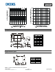
Fig.1 Typical Forward Characteristics
0.1
1
10
100
1,000
10,000
0 0.2 0.4 0.6 0.8
V , INSTANTANEOUS FORWARD VOLTAGE (V)
F
I , INSTANTANEOUS FORWARD CURRENT (mA)
F
T = -65°C
A
T = 100°C
A
T = 150°C
A
T = -65°C
A
T = 25°C
A
T = 75°C
A
T = 100°C
A
T = 125°C
A