
Instruction Manual

SBR30A45CTB
Document number: DS31527 Rev. 7 - 2
2 of 4
www.diodes.com
July 2011
© Diodes Incorporated
SBR30A45CTB
SBR is a registered trademark of Diodes Incorporated.
Maximum Ratings @T
A
= 25°C unless otherwise specified
Single phase, half wave, 60Hz, resistive or inductive load.
For capacitance load, derate current by 20%.
Characteristic Symbol Value Unit
Peak Repetitive Reverse Voltage
Working Peak Reverse Voltage
DC Blocking Voltage
V
RRM
V
RWM
V
RM
45 V
Average Rectified Output Current @ T
C
= 150ºC I
O
30 A
Non-Repetitive Peak Forward Surge Current 8.3ms
Single Half Sine-Wave Superimposed on Rated Load
I
FSM
175 A
Repetitive Peak Avalanche Power
(1µs, 25ºC)
P
ARM
8000 W
Thermal Characteristics
Characteristic Symbol Value Unit
Maximum Thermal Resistance (per leg)
Thermal Resistance Junction to Case
Thermal Resistance Junction to Ambient (Note 4)
R
θJC
R
θJA
1.5
16
°C/W
Operating and Storage Temperature Range
T
J
, T
STG
-65 to +150 ºC
Electrical Characteristics @T
A
= 25°C unless otherwise specified
Characteristic Symbol Min Typ Max Unit Test Condition
Forward Voltage Drop (per leg)
V
F
-
-
-
-
0.55
0.52
V
I
F
= 15A, T
J
= 25ºC
I
F
= 15A, T
J
= 125ºC
Leakage Current (Note 5)
I
R
-
-
-
-
0.5
100
mA
V
R
= 45V, T
J
= 25ºC
V
R
= 45V, T
J
= 125ºC
Notes: 4. Device mounted on additional heatsink, (Black Aluminum, 50mm x 37mm x 15mm)
5. Short duration pulse test used to minimize self-heating effect.
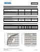
0 100 200 300 400 500 600 700
Fig.1 Typical Forward Characteristics
V , INSTANTANEOUS FORWARD VOLTAGE (mV)
F
0.0001
0.001
0.01
0.1
1
10
100
I, I
N
S
T
A
N
T
A
N
E
O
U
S
F
O
R
WA
R
D
C
U
R
R
E
N
T
(A)
F
T = -55°C
A
T = 25°C
A
T = 125°C
A
T = 150°C
A
T = 85°C
A
0.1
1
10
100
1,000
10,000
100,000
0 5 10 15 20 25 30 35 40 45
Fig. 2 Typical Reverse Characteristics
V , INSTANTANEOUS REVERSE VOLTAGE (V)
R
I , INSTANTANEOUS REVERSE CURRENT (uA)
R
T = -55°C
A
T = 25°C
A
T = 85°C
A
T = 125°C
A
T = 150°C
A