
Manual

ZLDO485
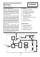
1). Operation From A Low Voltage
Battery Pack
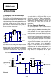
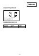
Fig.1 shows the ZLDO485 regulator being used
to stabilise the output of a 6V battery pack. The
ultra low dropout voltage of only 100mV at full
load (300mA) given by the regulator allows the
minimum number of cells to be used in the
pack and also maximises the energy that can
be removed from the battery before the output
of the regulator starts to fail.
At a load current of 100mA the dropout voltage
falls to around 30mV. The endurance of the
battery pack is not only dependent on dropout
voltage. When operating, some low dropout
regulators can consume high quiescent
currents, sometimes approaching as much as
a tenth of their maximum load current
specification when approaching dropout
conditions. Despite its 300mA output rating,
when enabled the ZLDO485 consumes
typically only 630uA regulating normally and
3mA when the input falls too low for
regulation.
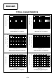
2). Post Converter Regulation
A common problem with multiple output
switch mode converters is that only one output
can be used in the feedback control loop of the
switching regulator. Thus only one output is
fully regulated. All other outputs are prone to
tracking errors that occur if the load on any
output change significantly. By ensuring close
coupling of all transformer windings and
minimising the impedance of all outputs, these
errors can be reduced but never eliminated. A
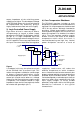
simple way round this problem is to wind the
switching regulator transformer to give a
slightly higher voltage than required and
regulate down from this to the desired voltage
with a linear regulator. This is indicated in
Figure 2. To keep losses low and so maintain
the advantages of a switch mode supply, it is
important that the voltage drop across this
regulator is kept as low as possible, i.e. just
high enough to compensate for the poor
APPLICATIONS
Spg
D/C
Vout
LBF
SC
Vin
N/C
Gnd
ZLDO485
6V
C2
1uF
C1
10pF
C3
100nF
Output
+4.85V
0V
Figure 1
Spg
D/C
Vout
LBF
SC
Vin
N/C
Gnd
ZLDO485
C2
1uF
C1
10pF
+12V Out
0V Out
C4
220uF
C5
220uF
+4.85V Out
TR1
Feedback
Switching
Regulator
Voltage
D1
D2
Figure 2
4-76