
User manual
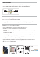

If attaching the Powerhouse to a pipe or post using the pipe bracket, first ensure the pole is strong enough to support the
weight of the Powerhouse then proceed as follows:
•
Establish the correct position for the Mightylite Pro on the pipe ensuring the wires can easily reach the unit.
•
Position the pipe bracket and U bracket around the pipe and secure using appropriate nuts bolts and washers (included),
as shown in [Fig.5].
•
Offer the Powerhouse up to the U bracket and secure using the securing bolts, spring washers and washers
provided [Fig.2].
•
Loosen the 4 screws holding the front of the connection box in place, and remove.
•
Feed the wire through the cable gland, gently tightening gland nut up against the gland body [Fig. 4] to ensure the
wire(s) is secured in place and no water can get though into the connection box.
•
Wire the Powerhouse as described in Section 4.
•
Once the power cable has been fed through the cable gland, approximately 6mm of insulation should be stripped
from each of the cores of AC cable ready to attach it to the terminal block in the front of the light fitting.
NOTE: The Diodor LED Powerhouse DIO-FL120W-WM and DIO-FL200W-WM are Class 1 fittings and therefore need to be
Earthed
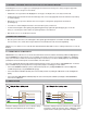
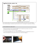
4.1 CONNECTING TO POWER SUPPLY
IMPORTANT: Diodor LED Powerhouse has two dual channel drivers which control the 4 LED arrays within the Mightylite Pro.
The four BROWN (Live) wires in the Powerhouse terminal, each operate as the Live for each of the LED arrays, enabling the
arrays to be wired to be switched on and off independently of each other (See Section 4.2 Wiring Options). The two BLUE
(Neutral) wires in the terminal operate as the Neutral for each of the drivers.
The unit is supplied with all 4 wires linked into 2 terminals which are, in turn, connected by a single BROWN wire. To wire the
unit so all 4 LED arrays operate together from a single switch (Single Level wiring) proceed as follows:
•
Connect the BROWN or RED (Live) wire to either terminal (marked “L”) holding 2 BROWN wires in the floodlight unit,
and linked together by a single BROWN wire [Fig.6].
•
Connect the BLUE or BLACK (Neutral) wire to the terminal (marked “N”) holding the 2 BLUE wires in the floodlight unit
[Fig.6].
•
Connect the YELLOW/GREEN or BARE (Earth) wire to the terminal (marked “EARTH”) holding the YELLOW/GREEN
wire in the floodlight unit
Note: One switch operates the Powerhouse which is always
at full power (100% light level) when switched on.
Note: One switch operates two of the Powerhouse LED arrays,
and another controls the other two arrays, enabling the unit to
operate at 50% or 100% power dependent on switching.
3.2. OPTION
2: ATTACHING THE Diodor LED Powerhouse VIA THE PIPE BRACKE
T
4. WIRING THE
FLOODLIGHT
4.2
WIRING OPTIONS
7
Live
Neutral