
Datasheet


S40 ... S500
Characteristics Kennwerte
Max. average forward rectified current
Dauergrenzstrom
T
A
= 50°C I
FAV
0.8 A
1
)
Forward voltage – Durchlass-Spannung T
j
= 25°C I
F
= 0.4 A
I
F
= 0.8 A
V
F
V
F
< 0.95 V
2
)
< 1.10 V
2
)
Leakage current – Sperrstrom T
j
= 25°C V
R
= V
RRM
I
R
< 5 µA
Thermal resistance junction to ambient air
Wärmewiderstand Sperrschicht – umgebende Luft
R
thA
< 60 K/W
1
)
Thermal resistance junction to terminal
Wärmewiderstand Sperrschicht – Anschluss
R
thT
< 20 K/W
Type
Typ
Recomm. protective resistance
Empf. Schutzwiderstand
R
t
[Ω]
3
)
Admiss. load capacitor at R
t
Zul. Ladekondensator mit R
t
C
L
[µF]
4
)
S40 2.00 2500 0.005
S80 4.00 1250 0.005
S125 6.25 800 0.005
S250 15.00 333 0.005
S380 20.00 250 0.005
S500 25.00 200 0.005
1 Mounted on P.C. Board with 25 mm
2
copper pads at each terminal
Montage auf Leiterplatte mit 25 mm
2
Kupferbelag (Lötpad) an jedem Anschluss
2 Valid per diode – Gültig pro Diode
3 R
t
= V
RRM
/ I
FSM
R
t
is the equivalent resistance of any protective element which ensures that I
FSM
is not exceeded
R
t
ist der Ersatzwiderstand eines jeglichen Schutzelementes, welches ein Überschreiten von I
FSM
verhindert
4 C
L
= 5 ms / R
t
If the R
t
C
L
time constant is less than a quarter of the 50Hz mains period, C
L
can be charged completely in a
single half wave of the mains. Hence, I
FSM
occurs as a single pulse only!
Falls die R
t
C
L
Zeitkonstante kleiner ist als ¼ der 50Hz-Netzperiode, kann C
L
innerhalb einer einzigen
Netzhalbwelle komplett geladen werden. I
FSM
tritt dann nur als Einzelpuls auf!
2 http://www.diotec.com/ © Diotec Semiconductor AG
R
t
3)
C
L
4)
~
~
+
_
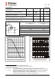
Rated forward current versus ambient temperature
Zul. Richtstrom in Abh. von der Umgebungstemp.
I
FAV
[%]
120
100
80
60
40
20
0
[°C]
T
A
150100
50
0
10
10
1
10
10
2
-1
-2
[A]
I
F
Forward characteristics (typical values)
Durchlasskennlinien (typische Werte)
0.4
V
F
0.8
1.0
1.2
1.4
[V] 1.8
T = 25°C
j
T = 125°C
j
30a-(1a-1.2v)