TECHNICAL INSTRUCTIONS PHRV HEAT PUMP WITH HYDRAULIC EQUIPMENT AIR / WATER 24 to 38 kW PHRV PHRV PHRV PHRV 22 25 32 36 CHGV cooling only model also available September 2007 10 12 162 - GB - 02
MARKING This product marked conforms to the essential requirements of the Directives: - Low voltage no. 2006/95/CE. - Electromagnetic Compatibility no. 89/336 EEC, modified 92/31 EEC and 93/68 EEC. - Pressure Equipment Directive No. 97/23/CE. CONTENTS 1 2 3 4 5 6 7 8 9 10 11 12 13 - Application - Use . . . . . . . . . . . . . . . . . . . . . . . . . . . . . . . . . . . . . . 2 Presentation . . . . . . . . . . . . . . . . . . . . . . . . . . . . . . . . . . . . . . . . . 3 Technical characteristics . . .
2 - PRESENTATION PHRV: Reversible heat pump with air evaporation with built-in hydraulic equipment. Refrigerant PHRV R 407C Model 1 refrigerant circuit 22 / 25 / 32 / 36 PHRV 9 5 4 b a 2 7 8 Water inlet 3 6 1 Water outlet 1 SCROLL COMPRESSOR 6 CIRCULATING PUMP • Mounted on vibration pads with sound insulation. • Resistance case. • Circulating pump with heat insulation. 7 EXPANSION TANK 2 WATER EXCHANGER 8 REFRIGERATION CIRCUIT • Plate water exchanger with heat insulation.
3 - TECHNICAL CHARACTERISTICS PHRV 22 PHRV 25 PHRV 32 PHRV 36 24 9 2.67 11.80 22.7 19.9 4.21 1.17 185 27.30 10.4 2.63 13.60 25.8 20.9 4.68 1.30 145 35.50 13.55 2.62 18.40 34 25 5.94 1.65 140 38.40 14.75 2.60 20 38.7 28.7 7.20 2 95 Available pressure kW A A m3/ h L/s kPa 20.80 8.85 2.35 11.80 22.7 18.6 3.49 0.97 215 25.80 9.7 2.66 13.60 25.8 20 4.5 1.25 160 30.30 13.55 2.24 18.40 34 27.3 5.22 1.45 200 33.50 14.55 2.3 20 38.7 29.3 6.05 1.
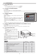
4 - PHYSICAL CHARACTERISTICS Dimensions (in mm) are given for standard units without options. General tolerance ±10 mm. Condenser air discharge Electrical connections Condenser air suction Location of the 4 anti-vibration pads (accessory) (100 x 100 x 25 mm) under girders a Chilled water inlet connection b Chilled water outlet connection c HP and LP hose entry G Centre of gravity (in the centre of the unit) 4.1 - PHRV • Clearances to be respected for unit operation and maintenance.
5 - DESCRIPTION Model Cooling circuit (number) with HP and LP pressure switches R 407 C refrigerant charge kg Hermetic SCROLL compressor with soundproofing and internal thermal protection Number Power supply 400V / 3 / 50Hz Nominal current per compressor Heating Cooling Nominal power consumed by the compressor Heating Cooling A A kW kW (*) (**) • • 1 1 1 1 • • • • • 1 9,800 760 620 1 9,800 760 620 1 11,000 760 660 1 11,000 760 660 • • • • A 3.5 3.5 3.9 3.9 kW 0.75 0.75 0.
6 - HEATING PERFORMANCES 50 35°C 45°C 50°C 46 42 TOTAL INPUT POWER Total input power (kW) PHRV 22 Heating capacity (kW) HEATING CAPACITY Water outlet temperature 38 34 30 26 -6 -4 -2 35°C 45°C 50°C 46 42 Water outlet temperature 38 34 30 26 11 10 -10 -8 18 -6 -4 -2 35°C 45°C 50°C 17 16 15 0 2 4 6 8 10 12 14 Outdoor wet bulb temperature (°C) Water outlet temperature 14 13 12 11 10 7 -10 -8 50 -6 -4 -2 35°C 45°C 50°C 46 42 6 0 2 4 6 8 10 12 14 Outdoor wet bulb temperature
7 - COOLING PERFORMANCES TOTAL INPUT POWER 60 55 50 45 Out. Out. Out. Out. temp. temp. temp. temp. 7 8 = = = = Total input power (kW) PHRV 22 Cooling capacity (kW) COOLING CAPACITY 15°C 25°C 35°C 45°C 40 35 30 25 20 4 5 6 9 10 11 12 13 14 15 Water outlet temperature (°C) 60 55 50 45 Out. Out. Out. Out. temp. temp. temp. temp. 7 8 Out. Out. Out. Out. temp. temp. temp. temp.
8 - CORRECTIONS TO BE MADE WHEN USING ANTI-FREEZE • IMPORTANT: Use monopropylene glycol; a minimum rate of 15% to 20% is needed to avoid any risk of corrosion. PRINCIPLE OF USING THE CURVES Correction factors A - Choose the percentage of glycol according to the minimum temperature to protect the hydraulic circuit against frost. B - Example: Protection at an external temperature of -15°C, which gives 30% glycol (freezing points curve).
11 - ACCESSORIES 11.1 - ANTI-VIBRATION KIT • Kit includes: - 1 set of 4 anti-vibration plates, thickness 25 mm - code 70600035. - 1 set of 2 flexible hoses: length 1 m, Ø 1" 1/4 - code 70600027. 11.2 - HP AND LP PRESSURE GAUGES • Code 70970007. • The accessory includes 1 set of 2 pressure gauges (HP and LP). • These elements, mounted on the vertical members of the unit's front face, display the high and low pressure values for each refrigeration circuit. 11.3 - REMOTE CONTROL • Code 70250055.
Auxiliary electric heating: • The heater consists of immersion heaters each rated at 8 kW (400 V, 3-phase), mounted on the tank. • These immersion heaters are controlled from a specific unit with 2-stage control, and the power feeders are protected by circuit breakers and a master switch (power supply separated). • Backup is authorized with the 2nd stage, although is triggered only if the generator is out of service. • The power supply for this heating system is connected separately (3-phase 400 V).
13 - INSTALLATION INFORMATION • See details in the installation manual. 13.1 - INSTALLATION • Protection index of the unit: : for the electrical equipment, - IP 24 (IPXXB : for the mechanical hazards). • Before installation, verify the following points: - the unit must be installed outside in an appropriate location and in compliance with environmental requirements (sound level, integration, etc...