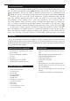
Direct Airscale easy series Code : from 1835 to 1866 TECHNICAL INSTRUCTIONS May change without notice First 162 install Kit 1.62m 1.26m ASYMM YES install Kit 21dm2 2.3kg 3.
CONGRATULATIONS. Thank you for choosing Direct Airscale model. If you have any problems do not hesitate to consult our website. Especially the section CLUB DA (Direct Airscale club) for each plane where you will find information. You also can consult us directly by phone but try to be a maximum shorter . Thank you. You also can participate in the interaction you’ll find at general chapter CLUB DA. The first (your first one) is the specific airplane for beginner. Rectangular wing with lift wing edge.
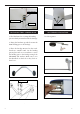
HINGING THE AILERON. Epoxy Note : The control surfaces, including the ai- lerons, elevators, and rudder, are prehinged with hinges in stalled, but the hinges are not glued in place. It is imperative that you properly adhere the hinges in place per the steps that follow using a high-quality thin C/A glue. 1) Carefully remove the aileron from one of the wing panels. Note the position of the hinges. 4) Deflect the aileron and completely saturate each hinge with thin C/A glue.
HINGING THE ELEVATOR. 1) Locate the item for this section of the manual. 2) Carefully remove the elevator from one of the horizontal stabilizer panels. Note the position of the hinges. 5) Turn the wing panel over and deflect the aileron in the opposite direction from the opposite side. Apply thin C/A glue to each hinge, making sure that the C/A penetrates into both the aileron and wing panel.
WING ASSEMBLY. See below pitures. Aluminium wing tube WING ASSEMBLY. See below pitures. Knife.
Cut Epoxy Epoxy . INSTALLING THE AILERON SERVO. . 1) Install the aileron servo into the servomount, with the output shaft towards the leading edge of the wing, using the wood screws provided with your radio system. Drill 1/16” pilot holes through the mount before installing the screws. This will prevent the wood from splitting. INSTALLING THE AILERON LINKAGE. See below pitures.
Wire keeper. Pushrod wire Fuel tank INSTALLING THE LANDING GEAR. 1) The blind nuts for securing the landing gear are already mounted inside the fuselage. M4x20mm NOSE GEAR INSTALLATION. See below pitures. 2) Using the hardware provided, mount the main landing gear to the fuselage. 3) Place the fuselage inverted on the workbench in a suitable stand. Set the landing gear in place and use a screwdrive to secure the landing gear to the fuselage using bolts M4x20mm and washers.
2) Use balsa plywood to help prevent moveable from transferring to the fuel tank as shown. C/A glue A FUEL TANK INSTALLATION. Fuel tank. B A B You should mark which tube is the vent and which is the fuel pickup when you attach fuel tubing to the tubes in the stopper. Once the tank is installed inside the fuselage, it may be difficult to determine which is which C/A glue Balsa wood included. Vent tube. 1) Slide the fuel tank into the fuselage.
THROTTLE SERVO ARM INSTALLATION. Install adjustable servo connector in the servo arm as same as picture below: Adjustable servo connector. Loctile secure. Servo arm. Blow through one of the lines to ensure the fuel lines have not become kinked inside the fuel tank compartment. Air should flow through easily. Elevator servo. Throttle servo arn. INSTALLING THE FUSELAGE SERVOS. Because the size of servos differ, you may need to adjust the size of the precut opening in the mount.
Switch. 2mm MOUNTING THE ENGINE. + ENGINE .46- .55 : 2 STROKE 4) On the fire wall has the location for the throttle pusshrod tube (pre-drill). 1) Position the engine with the drive washer (110mm) forward of the firewall as shown. 2mm 110 mm 2) Use a pin drill and 2mm drill bit to drill a small indentation in the mount for the engine mounting screw. 5) Slide the pushrod tube in the firewall and guide it through the fuel tank mount.
Machine screw M3x25mm 8) Reinstall the servo horn by sliding the connector over the pushrod wire. Center the throttle stick and trim and install the servo horn perpendicular to the servo center line. 9) Move the throttle stick to the closed position and move the carburetor to closed. Use a 2.5mm hex wrench to tighten the screw that secures the throttle pushrod wire. Make sure to use threadlock on the screw so it does not vibrate loose. ELECTRIC POWER CONVERSION.
Blind nut Blind nut 3mm 4mm M4x60 mm 4mm 12
Speed control Battery 2) While keeping the back edge of the cowl flush with the marks, align the front of the cowl with the crankshaft of the engine. The front of the cowl should be positioned so the crankshaft is in nearly the middle of the cowl opening. Use the spinner backplate as a guide. Hold the cowl firmly in place using pieces of masking tape.
HORIZONTAL STABILIZER. 1) Using a ruler and a pen, locate the centerline of the horizontal stabilizer, at the trailing edge, and place a mark. Use a triangle and extend this mark, from back to front, across the top of the stabilizer. Also extend this mark down the back of the trailing edge of the stabilizer. 3x10mm Draw center line 2) Using a modeling knife, carefully remove the covering at mounting slot of horizontal stabilizer.
5) When you are satisfied with the alignment, hold the stabilizer in place with T- pins or masking tape, but do not glue at this time. 6) With the stabilizer held firmly in place, use a pen and draw lines onto the stabilizer where it and the fuselage sides meet. Do this on both the right and left sides and top and bottom of the stabilizer. 8) Using a modeling knife, carefully remove the covering that overlaps the stabilizer mounting platform sides in the fuselage.
Epoxy 3) Slide the vertical stabilizer back in place. Using a triangle, check to ensure that the vertical stabilizer is aligned 90º to the horizontal stabilizer. Pen 2) Using a modeling knife, remove the covering from over the precut hinge slot cut into the lower rear portion of the fuselage. Knife 3) When you are sure that everything is aligned correctly, mix up a generous amount of Flash 30 Minute Epoxy.
Pen ELEVATOR - RUDDER CONTROL HORN. 8mm 2x12mm Rudder control horn. 2x12mm Elevator control horn. ELEVATOR PUSHROD HORN INSTALLATION. Control horn Elevator pushrod RUDDER PUSHROD HORN INSTALLATION.
Pen Battery Receiver. ATTACHMENT WING-FUSELAGE. 8mm Cut INSTALLING THE BATTERYRECEIVER. 1) Plug the five servo leads and the switch . lead into the receiver. Plug the battery pack lead into the switch also. 2) Wrap the receiver and battery pack in the protective foam rubber to protect them from vibration. 3) Route the antenna in the antenna tube inside the fuselage and secure it to the bottom of fuselage using a plastic tape.
BALANCING. 1) It is critical that your airplane be balanced correctly. Improper balance will cause your plane to lose control and crash. THE CENTER OF GRAVITY IS LOCATED 70MM BACK FROM THE LEADING EDGE OF THE WING AT THE WING ROOT. 2) Mount the wing to the fuselage. Using a couple of pieces of masking tape, place them on the top side of the wing 70mm back from the leading edge of the wing at the wing root. 3) Turn the airplane upside down.
MAIDEN FLY. We will not give you any instructions in this part. This is not the role of a manufacturer and it would be unrealistic and even dangerous to think we can make adjustments prior to first flight just by reading a document. It necessarily requires a minimum of experience and you must get closer to a driver or experienced trainer. This will verify the magnitude and direction of the control and various other settings. Also good battery recharging, fuel quality and other studio and field accessories.