
Instructions / Assembly

27en
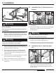
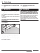
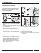
6. Slide the transmitter (4) over the head of the carriage
bolt M6 (1) and tighten the wing nut M6 (2). The position
of the photo eyes can be adjusted through the slotted
holes (5).
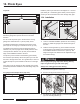
7. Mount the receiver on the opposite side in the same way.
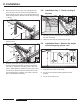
8. Run the two sets of wires (6) from the photo eyes to the
control housing.
9. Use staples to keep wires in place.
10.5. Connection
Connect photo eyes to the control housing
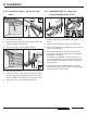
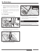
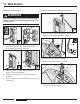
1. Remove the red cover (1) of the control housing (2).
2. Strip off insulation approx. 3/8“ (10 mm) from the wire
ends (transmitter and receiver).
2
1
14
15
16
R
13
3
4
5
6
1
3
2
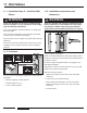
3. Guide both sets of wires (1) from the outside through the
opening (2) into the control housing (3).
4. Connect one wire of the transmitter to terminal 5 and the
other wire to terminal 6.
5. Connect one wire of the receiver to terminal 5 and the
other wire to terminal 6.
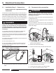
Note
If you have inadvertently inserted a wire end incorrectly,
you can open the terminal using a small slotted screwdriver
(press down) and pull out the wire end.
10. Photo Eyes