Pro9F Floor Plate Automotive Lift 9,000 POUND CAPACITY IMPORTANT Reference ANSI/ALI ALIS, Safety Requirements for Installation and Service of Automotive Lifts before installing lift. INSTALLATION / OWNERS MANUALS Read this manual thoroughly before installing, operating, or maintaining this lift. When done with installation, be sure to return documents to package and give all materials to lift owner/operator.
TABLE OF CONTENTS • • • • • • • • • • • • • • • IMPORTANT INFORMATION..................................................................... 2 GENERAL LIFT INFORMATION / FEATURES.......................................... 3 LIFT SPECIFICATIONS:............................................................................. 4 LIFT AREA LAYOUT INFORMATION........................................................ 5 FOUNDATION and ANCHORING REQUIREMENTS ................................
CAUTION!! ENSURE THAT ALL CABLE SHEAVES, BEARINGS, AND SHAFTS ARE SUFFICIENTLY LUBRICATED. ALSO, THE CORNERS OF EACH COLUMN SHOULD BE LIGHTLY GREASED WITH QUALITY LITHIUM GREASE PRIOR TO OPERATING THE LIFT. LUBRICATE ALL ON AN ANNUAL BASIS. Motors and all electrical components are not sealed against the weather and moisture. Install this lift in a protected indoor location.
LIFT SPECIFICATIONS Capacity Overall Height Overall Floor Width Maximum Lift Height Minimum Adapter Height Between Columns Drive Thru Motor 9,000 lbs. (2,250 lbs per Arm) 111-1/4" 138-1/2" 81" 4" 111" 97-1/4" 2HP, 208 - 230 VAC, 1PH 138-1/2” 46-1/4” Max Arm Reach 30” Min Arm Reach 16” 111” 107” 111-1/4” 97-1/4” Drive-thru Clearance 4” Adapter Height 1-1/2” Drive Over Pro9F 9000 lbs. Floor Plate Lift 4 IN50019 Rev.
LIFT AREA LAYOUT INFORMATION (Symmetrical Arm configuration) 6' 0" (1829mm) minimum to nearest obstruction or bay. 7' 0" (2134mm) minimum to nearest wall. APPROACH 12' 0" (3658mm) minimum to nearest obstruction 12' 0" (3658mm) minimum to nearest obstruction Power Unit NOTE: Lift can be installed so power unit can column can be located on either side. However, to save operation steps it is recommended that it is placed on passenger side of lift. Pro9F 9000 lbs. Floor Plate Lift 5 IN50019 Rev.
FOUNDATION and ANCHORING REQUIREMENTS 1. Concrete shall have compression strength of at least 3,000 PSI and a minimum thickness of 4” in order to achieve a minimum anchor embedment of 3 1/4”. NOTE: When using the standard supplied 3/4” x 5 1/2 long anchors, if the top of the anchor exceeds 2 1/4” above the floor grade, you DO NOT have enough embedment. 2. Maintain a 6” minimum distance from any slab edge or seam. Hole to hole spacing should be a minimum 61/2” in any direction.
TOOLS & EQUIPMENT REQUIRED FOR INSTALL The installation of this lift is relatively simple and can be accomplished by two men in a few hours. The following tools and equipment are needed: • • • • • • • • • • • Hoist or Forklift (optional) Two 10’ to 12’ step ladders ISO 32 Light Hydraulic Oil (approx.
INSTALLATION PROCEDURE STEP 1: After unloading the lift, place it near the intended installation location. STEP 2: Remove the shipping bands and packing materials from the unit. The Power Unit will be unpacked from the top. Note: Be careful not to drop power unit. STEP 3: Remove the packing brackets and bolts holding the two columns together (do not discard bolts; they are used in the assembly of the lift).
2. Keep the drill in a perpendicular line while drilling. 3. Let the drill do the work. Do not apply excessive pressure. Lift the drill up and down occasionally to remove residue to reduce binding. 4. Drill the hole to depth equal to the length of anchor. Note: Drilling thru concrete (recommended) will allow the anchor to be driven thru the bottom of foundation if the threads are damaged or if the lift will need to be relocated. 5. For better holding power blow dust from the hole.
STEP 10: Installing the equalizing cables: (see diagram below) Loosen the two Cable Retaining Bolts as shown. Route the first cable as shown. Tighten nut on one cable stud so that the end of stud passes the nylon on the nut. Pull the other end of cable and run nut on it. Repeat above for second cable. Once installed tighten the Cable Retaining Bolts. NOTE: DO NOT tighten cables at this time. Just start them on the threads.
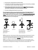
STEP 11: Cylinder centering and chain installation: Make sure the “Tip” on the bottom of the cylinder is properly located into the center hole on top of the cylinder mount in base. STEP 12: Connect the Hydraulic Hoses and Fittings, as shown. Power Unit 90º Fitting Hydraulic Cylinder Hydraulic Hose Hydraulic Nipple Hose Hydraulic Nipple M6 x 8 Screw Hose Clip 90º Fitting Hydraulic Extension Pro9F 9000 lbs. Floor Plate Lift 11 IN50019 Rev.
STEP 13: Mount the Power Unit on lift as shown. STEP 14: Mount the Floor Plate as shown below. Drill 3/8" holes using holes in plate as guides. Following drill steps/directions used when anchoring columns. Tighten to 25 ft-lbs. 3/8” Anchor Floor Plate STEP 15: Install the swing arms on the carriages using the included 1-1/2" diameter pins. Check for proper engagement of the arm lock – the teeth on the lock should fully engage the gear on the arm.
STEP 17: Remove the vented fill cap from the power unit and fill the reservoir. Use a Ten Weight (ISO AW32) non-foaming, non-detergent hydraulic fluid (i.e. Texaco HD32 or equal). The unit will hold approximately twelve quarts of fluid. If a replacement fill cap is required order from your distributor, a vented cap MUST be used. STEP 18: Make the Electrical hookup to the power unit; 220V Single Phase.
The Owner / Employer: • Shall ensure that lift operators are qualified and that they are trained in the safe use and operation of the lift using the manufacturer’s operating instructions; ALI/SM01-1, ALI Lifting it Right safety manual; ALI/ST-90 ALI Safety Tips card; ANSI/ALI ALOIM-2000, American National Standard for Automotive Lifts-Safety Requirements for Operation, Inspection and Maintenance; ALI/WL Series, ALI Uniform Warning Label Decals/Placards; and in the case of frame engaging lifts, ALI/LP-GUIDE,
Employees authorized to perform lockout shall ensure that the appropriate energy isolating device (i.e., circuit breaker, fuse, disconnect, etc.) is identified for the lift being locked out. Other such devices for other equipment may be located in close proximity of the appropriate energy isolating device. If the identity of the device is in question, see the shop supervisor for resolution. Assure that proper authorization is received prior to performing the lockout procedure.
• When approaching the lift with a vehicle, make sure to center the vehicle between the columns so that the tires will clear the swing arms easily. Slowly drive the vehicle between the columns. It is recommended to have someone outside the vehicle guide the driver. • Always lift vehicle using all four pads. • Never use lift to raise one end or side of vehicle. • Always raise vehicle about 3” and check stability by rocking vehicle.
Ensure lift operators review safety and warning labels prior to operating lift. Pro9F 9000 lbs. Floor Plate Lift 17 IN50019 Rev.
Safety and Operating Instructions Only authorized personnel are to operate lift Read operating and safety procedures manual completely before operating lift. • Properly maintain and inspect lift in accordance to owner’s manual. • Do not operate a lift that is damaged or in need of repair. • Allow only authorized personnel in the lift bay. • Stay clear of Lift when raising or lowering (NO RIDERS) • Keep hands and feet away from pinch points at all times.
Refer to the manufacturer’s specific vehicle lifting points. Some vehicles display these points on a label inside the right front door lock face or are identified by triangle shape marks on the vehicle’s undercarriage, reference SAE J2184. PREVENTIVE MAINTENANCE SCHEDULE The periodic Preventive Maintenance Schedule given is the suggested minimum requirements and minimum intervals; accumulated hours or monthly period, which ever comes sooner.
1. Check anchor bolts torque to 80 ft-lbs for the 3/4 in. anchor bolts. Do not use an impact wrench to tighten anchor bolts. 2. Check hydraulic oil level. 3. Check cylinder pulley assembly for free movement or excessive wear on cylinder yoke or pulley pin. 4. Check cable pulley for free movement and excessive wear. • Yearly Maintenance 1. Lubricate chains 2. Grease rub blocks and column surface contacting rub blocks 3.
TROUBLESHOOTING The common problems that may be encountered and their probable causes are covered in the following paragraphs: • Motor Does Not Operate Failure of the motor to operate is normally caused by one of the following: 1. Breaker or fuse blown. Repair or replace. 2. Faulty wiring connections; call electrician. 3. Defective up button; call electrician for service.
• Motor Hums and Will Not Run If the motor hums but fails to run, take the following actions: 1. Lift overloaded. Remove excessive weight from lift WARNING!! The voltages used in the lift can cause death or injury to personnel. In the following steps, make sure that a qualified electrician is used to perform maintenance 2. Faulty wiring..….... Call electrician 3. Bad capacitor..….. Call electrician 4. Low voltage........... Call electrician • Lift Jerks Going Up and Down 1.
ILLUSTRATED PARTS BREAKDOWN 91 15 14 44 45 45 44 3 43 43 Pro9F 9000 lbs. Floor Plate Lift 23 IN50019 Rev.
72 92 93 29 30 42 32 34 35 31 21 36 33 58 37 38 39 87 41 75 40 22 23 17 85 84 84 83 87 81 82 3 78 49 80 51 77 79 Pro9F 9000 lbs. Floor Plate Lift 24 IN50019 Rev.
13 20 14 18 48 91 14 15 17 15 16 18 14 62 72 3 1 60 88 63 87 87 12 94 95 11 10 9 50 6 51 8 Pro9F 9000 lbs. Floor Plate Lift 25 IN50019 Rev.
46 47 17 17 1 49 50 51 76 51 52 54 21 68 18 17 18 48 12 53 57 53 56 55 Pro9F 9000 lbs. Floor Plate Lift 26 IN50019 Rev.
91 15 14 44 45 45 44 3 43 43 Pro9F 9000 lbs. Floor Plate Lift 27 IN50019 Rev.
Parts List Items 1 3 6 8 9 10 11 12 13 14 15 16 17 18 20 21 22 23 29 30 31 32 33 34 35 36 37 38 39 40 41 42 43 44 45 46 47 Drawing GF-1000 GF-2000 GL-09-098 B14-3/4×150 B14-3/8×2.5 30400-1013 B23-6×8 P/U B10-12×50 B41-12 B40-12 B30-12 B60-25 30400-1005C GF-1500 YG07-9100 30400-5023 B52-2×20 GF-2100 30500-5200-4 DP9-3003 B51-6×40 30500-5300 30400-5020 B28-6×35 30400-5006-1 30400-5006-3 B31-20 B40-20 30400-5006 30400-5011 B11-20×50 GF-4000 B33-3/4-16 B41-20 52080 30400-9012-01 Pro9F 9000 lbs.
48 49 50 51 52 53 54 55 56 57 58 60 62 63 68 72 75 76 77 78 79 80 81 82 83 84 85 87 88 91 92 93 94 95 52005 B30-8 B40-8 B41-8 B10-8×35 30400-9054(B)YZ 1WB-06(GL-9000) 30500-9100G1 30400-9052YZ 1WB-01(30400-9030YZ) BL644×121P 52200-3 B13-6×28 B30-6 30400-9053YZ(SW-002) GF-1100 GF-2100DC 30400-1999 ETPF-2007 9B-4100 ETPF-2004 B33-8 GL-09-102 30400-5031 30400-5028 B40-36 B60-35 GF-3000 GF-6100 B11-12×30 GF-1005 B23-4×8 GF-1004 B11-8×15 Pro9F 9000 lbs. Floor Plate Lift 4.
Notes: Pro9F 9000 lbs. Floor Plate Lift 30 IN50019 Rev.
Notes: Pro9F 9000 lbs. Floor Plate Lift 31 IN50019 Rev.
Notes: Pro9F 9000 lbs. Floor Plate Lift 32 IN50019 Rev.