model 1200t
CONGRATULATIONS Congratulations for choosing a Directed Audio power amplifier from Directed Electronics, the industry leader in high quality automotive security and audio equipment since 1990. Directed Audio power amplifiers continue to set new standards of performance, reliability, and affordability in the mobile electronics industry.
LIMITED TWO-YEAR CONSUMER WARRANTY Directed Electronics, Inc. promises to the original purchaser, to replace this product should it prove to be defective in workmanship or material under normal use, for a period of two years from the date of purchase by the dealer as indicated by the date code marking of the product PROVIDED the product was installed by an authorized Directed dealer.
FEATURES High-speed MOSFET switching power supply and dual N-channel MOSFET outputs Stereo, mono, or simultaneous stereo/mono operation Top and side panel ESP I/O ports for connection for ESP-2 Security components and current Bitwriter module with Audio programming Thermal, DC offset, reverse polarity, short circuit and over/under voltage protection Continuously variable 12 dB/octave two-way crossover (Selectable 24 dB LP/mono mode) Variable 0-15 dB bass EQ function Top-mounted co
NOTE Prior to servicing your vehicle ensure that the alarm system is disarmed. Due to the amplifier’s anti-theft feature (if enabled), if the main power to the amplifier is removed while the alarm is armed the amplifier operation is disabled. The amplifier operation must then be reset by your Directed dealer. INSTALLATION GUIDELINES 1. Please read this owner's manual carefully before installing this amplifier. 2. Disconnect the battery ground terminal prior to making any electrical connections. 3.
cable of the vehicle, and if necessary, upgrade it by adding an additional ground wire that is the same gauge as the amplifier's power wire. Remember, the amplifier can only deliver its rated output when it is not current limited by the power and ground supply wires. 8. This amplifier is designed to drive a speaker load that measures from 1 to 8 ohms. Keep in mind that heat is the long-term enemy of automotive electronics and the lower your speaker load, the more heat is generated.
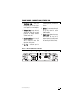
FRONT PANEL CONNECTIONS/STATUS LED 1. RCA Output Jacks - These pass through RCA jacks can be used to send a signal to a second amplifier. connecting external, 12v DC brushless fan. 5. ESP Port - For connecting the amplifier to ESP-2 alarm or second 1200T amplifier. 2. RCA Input Jacks - Accepts line level outputs from head units or signal processors at voltages between 250 mV and 8 volts. 6.
REAR PANEL CONNECTIONS 1. Speaker Out Terminals - Connect the speakers to these terminals. (Refer to the Speaker Connection section of this guide.) 2. Power LED - This LED will illuminate Green to indicate the amplifier is on and operating normally. The LED will extinguish if the amplifier is off or if the amplifier shuts-down due to short circuit, DC offset, or overheating. 3. One Ohm LED - This LED will illuminate when the 1-ohm mode is selected. 4.
FIGURE 2—AMPLIFIER CONNECTIONS 1200T REAR 2, 3 1 L 1 MIN R 4 5 6 7 FUSE 30A x 3 + BATT REM GND POWER BRIDGED 2 MIN ONE OHM TOP PANEL FEATURES Control Panel Cover Remove/Install The gain and filter controls are located under a control panel cover on top of the amplifier. The control panel cover must be removed to gain access to the gain and filter controls. Four Allen-head screws hold the control panel cover to the amplifier top panel, one at each corner.
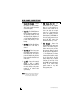
AMPLIFIER CONTROLS TOP 1. ESP Port - Allows programming of the amplifier using the Bitwriter®. 2. Subsonic Frequency Hz - This control adjusts the subsonic filter cutoff (between 15-50 Hz). 7. Bass Boost Adjust - 0 to 15 dB of additional bass boost. Rotating control clockwise increases bass boost. Amp Mode Switches 3. Subsonic Filter - The IN position places the subsonic filter into the system, the OUT position takes the filter out of the system. 8.
FIGURE 3—AMPLIFIER CONTROLS TOP ESP PORT 1 XOVER FREQ Hz SUBSONIC FREQ Hz 4 5 55 550 XOVER SLOPE 12 24 GAIN dB 15 50 IN OUT SUBSONIC FILTER NOTE: 3 BASS BOOST 6 8 2 7 MIN AMP MODE MAX 0 dB 15 MONO STEREO LOW FULL HIGH 9 The adjustment for Gain is a digital control (potentiometer). Although it will have the feel of adjustment like the other controls on this panel (there are no detents), the Gain control has 33 discrete steps in adjustment.
ESP FEATURES AND CONTROLS The ability to access the feature settings of your amplifier is only possible with the use of a Directed Electronics Bitwriter® unit. Firmware version 1.8 or later is required in the Bitwriter®. Versions prior to 1.8 will not program the amplifier. MAIN FEATURES 1. Turn-on delay - 0.75, 1.00, 1.25, 1.75, 2.25, 2.75, or 3.25 seconds is selectable. 2.75 seconds is the factory default setting. 2. Anti-theft - On/Off/Reset Anti-Theft Trigger.
SPEAKER WIRING DIAGRAMS Stereo operation (top view) Mono operation (top view) Simultaneous stereo/mono operation (top view) © 2004 Directed Electronics, Inc 13
CROSSOVER SETTINGS AND GAIN ADJUSTMENT Your Directed Audio power amplifier needs to be adjusted carefully to achieve maximum performance. These are some guidelines to follow when fine-tuning the amplifier. For full-range and simultaneous stereo/mono bass applications, the crossover selection switch should be set to FULL. If the amplifier is driving your subwoofers, set the switch to LOW, and for mid-bass/midrange output, set to HIGH.
SUBSONIC FILTER ADJUSTMENT This amplifier incorporates a subsonic filter to maximize the performance of a subwoofer. The subsonic filter is a high pass filter that removes unwanted bass output at very low frequencies from the woofer. This increases the output of a subwoofer by as much as 3 dB by increasing the mechanical power handling of the subwoofer.
SPECIFICATIONS Power Output: 200 Watts RMS X 2 Channels at 4 Ohms and < 1% THD+N Signal to Noise Ratio: 80 dBA (reference 1 Watt into 4 Ohms) 16 RMS continuous power per channel, driven in 4 ohm mode @ 14.4 VDC 225 Watts RMS @ 4 ohms 450 Watts RMS @ 2 ohms 900 Watts bridged @ 4 ohms RMS continuous power per channel, driven in 1 ohm mode @ 14.
RCA Input/Output Jacks 2-channel in/2-channel buffered full-range out Input Impedance 30K ohms Input Sensitivity Variable from 250 mV to 8 volts Supply Voltage 10 to 16 VDC Fusing and Power 30A (qty 3) Minimum Cable Requirements (AWG) #8 Dimensions 19 x 9¾ x 2 inches Port Output (Optional Fan) 12V @<200mA © 2004 Directed Electronics, Inc 17
The company behind this system is Directed Electronics, Inc. Since its inception, Directed has had one purpose, to provide customers with the finest vehicle security, car stereo products, rear seat entertainment, and accessories available. The recipient of more than 20 patents in the field of advanced electronic tech- Directed Electronics, Inc. Vista, California 92081 www.directed.com nology, Directed is ISO 9001 registered.