CS-222 2-Channel Main Station INSTRUCTION MANUAL *il I Clear-m r e OF intercom Systems 0 4065 Hollis St., Emeryville, CA 94608 (510) 496-6666 © Clear-Corn Intercom Systems 810133 9/25/91 REV.
Clear-Com CS-222 2-Channel Main Station O CLEAR-COM LIMITED WARRANTY Clear-Com products are warranted to be free from defects in materials and workmanship for a period of one year from the date of sale. Clear-Com's sole obligation during the warranty period is to provide, without charge, the parts and labor necessary to remedy covered defects appearing in products returned prepaid to Clear-Com, 945 Camelia St., Berkeley, Ca. 94710-1484, U.S.A.
Clear-Com CS-222 2-Channel Main Station Shipping IQManufacturer f Repair lr j l aimmnt All shipments of Clear-Com equipment must be prepaid via United Parcel Service or the best available shipper.
DESCRIPTION / Clear-Corn CS-222 2-Channel Main Station O SECTION 1 DESCRIPTION OF THE CS-222 2-CHANNEL INTERCOM STATION CLEAR-COM CONCEPT Clear-Com is a closed-circuit intercom system that consistently provides high-clarity communication in high-noise and low-noise environments. A basic system consists of a single- or multi-channel power supply or main station connected to various single- or multi-channel remote stations, such as beltpacks and loudspeaker stations.
DESCRIPTION / Clear-Com CS-222 2-Channel Main Station 1.1 CS-222 OVERALL DESCRIPTION The CS-222 is a portable, two-channel main station with a regulated power supply and a versatile monitoring system. Itfeatures excellent speech intelligibility in all noise-levels. The CS-222 contains a mic preamp with a limiter. The CS-222's four-watt power amp can drive a standard Clear-Com headset to levels greater than 110 dB SPL. The CS-222 provides DC voltage and the ability to talk & listen on two separate channels.
DESCRIPTION / Clear-Corn CS-222 2-Channel Main Station Monitoring System The front panel of the CS-222 has one headset connector for use by the operator. The operator monitors the intercom channels turning up the appropriate "Listen Level" volume controls (one for Channel A, one for Channel B). Either channel may be monitored separately, or both simultaneously (without tying the two channels together). These volume controls are always active regardless of "Talk" channel selection on the station.
DESCRIPTION / Clear-Corn CS-222 2-Channel Main Station LINKino Channels Taethe A front panel switch is provided that allows the operator to instantly connect channel A and channel B together for a combined intercom system consisting of both channels. Reonte Mk-Kill Function The CS-222 provides the ability to turn off any open-mics on Series 500 belt-pack remote stations.
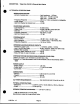
DESCRIPTION / Clear-Com CS-222 2-Channel Main Station O 1.2 TECHNICAL SPECIFICATIONS: MICROPHONE PRE-AMP: --Dynamic Headset Input: ------------------------ Input Impedance - 1 KOhms Input Level - -55 dBv* nominal Input Level - -10 dBv* max. --Frequency Response: --------------------------- 250 Hz to 12 KHz, contoured for intelligibility.
INSTALLATION I Clear-CoM CS-222 2-Channel Main Station SECTION 2 INSTALLATION OF THE CS-222 2-CHANNEL MAIN STATION 2.1 INSTALLATION OVERVIEW The CS-222 is a combination of a very versatile intercom station and a system power supply. Installations can vary depending on what features are used. The fundamental concept of Clear-Com Party-Line intercom isthat all stations provide high impedance current sourced signals into a single common system termination.
INSTALLATION I Clhar-Corn CS-222 2-Channel Main Station SYSTEM POWERING: Typical Clear-Com systems consist a a MAIN STATION and multiple REMOTE STATIONS. The REMOTE STATIONS are powered from the MAIN STATION through the Intercom cable. RS-501 CC-75B RS-501 CC-75B RS-SO1 CC-75B RS-5O1 CC-758 TERMINATONS ON TO OTHER LEL .
INSTALLATION / Clear-Com CS-222 2-Channel Main Station 2.2 CABLE CONSIDERATIONS: The Clear-Com intercom line is intended to run on a shielded twisted pair of cable per channel of intercom. One conductor carries full duplex ("two-way") audio, the other conductor carries the DC power for remote stations. The shield is used for ground return for audio and power. When choosing interconnect cable, keep the following considerations in mind: 1. DC resistance of the ground or common conductor affects crosstalk.
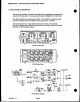
INSTALLATION / Clear-Com CS-222 2-Channel Main Station * 2.3 REAR PANEL DESCRIPTION CIL SS CS-222 Rear Panel 1. Power Swltch The AC "Power Switch" is located on the top left corner of the rear panel. The switch is a rocker switch with a "1"n mark for on and "0"for off. i w 2. Power Connector Just below the power switch is an EIA power receptacle for either 115 or 230 VAC ~~~power input. ~~3. Power Voltage Select and Fuse Block Just below the EIA receptacle is a plug-in fuse block.
INSTALLATION / Clear-Corn CS-222 2-Channel Main Station 6. Announce Output Connector The "Announce" output is a XLR-3M. The output is transformer isolated, 600 ohms output impedance, and has an output level of approximately 0 dBv. Wiring is as follows: Pin 1 -- Ground Pin 2 --- Audio Pin 3 -- +Audio 7. Announce Relay Contact Terminals The "Announce" relay contacts are available on a screw terminal block. The relay contacts are "Form C" (break before make).
INSTALLATION / Clear-Com CS-222 2-Channel Main Station 'CAUTION These servicing Instructions am usr by nualified service personnel onl at AmiX electric shock t d nat erfofnMy servicing hor than tat contained in ft Qaurating Insrutlnions unless u AM nualifled lt do s2,a 2.4 INTERNAL OPTIONS AND ADJUSTMENTS ACCESS TO INTERNAL OPTIONS AND ADJUSTMENTS: To access the internal options and adjustments the cover of the unit must be removed. Remove the handle by removing the two screws securing R.
INSTALLATION / Clear-Com CS-222 2-Channel Main Station F 2.5 INTERCONNECTION SETUP 0 After determining system configuration and channel assignment, pick a location for the CS-222; it can be anywhere as long as it is provided with a source of AC power. Check the Power Block on the rear panel for the proper AC voltage range. See section 2.3 on the page 12 if it needs changing. 1. Use standard shielded mic cable (see section 2.2).
INSTALLATION / Clear-Com CS-222 2-Channel Main Station TYPICAL CS-222 SYSTEMS: K9-111A K9-1-1A KS-11iA RS C 75 R 9 CC-75B RS-502 RSd 11/90 Rev. 1.
OPERATION / Clear-Com CS-222 2-Channel Main Station SECTION 3 / OPERATION OF THE CS-222 2-CHANNEL INTERCOM STATION Normal operation of the CS-222 only requires access to the front panel controls. For intercom operation set the Listen Level controls for each channel to desired level and press the Talk switches when talking. The rest of this section is a detailed description of each control. 3.1 FRONT PANEL DESCRIPTION CS-222 Front Panel 1.
OPERATION I Clear-Corn CS-222 2-Channel Main Station 0 3. Listen Level Controls Each channel has a separate "Listen Level" control. Listening Is always on and Is not controlled by any logic. To listen to a channel, turn up the appropriate control. To not listen to a channel, turn the control completely off. 4. Side Tone Controls Each channel has a "Side Tone" null control. This control is used to set the amount of the microphone that is heard Inthe earphone from that channel.
OPERATION / Clear-Com CS-222 2-Channel Main Station 9. Earphone Jack The jack marked "Earphone" provides an output intended to drive an extra earphone. This output iscapable of driving an 8 ohm headphone or loudspeaker. 10. Link Switch The switch marked "Link" on the right side of the unit allows the operator to "combine" channels A and B so that all stations can talk to each other. (Normally channels A and B are totally isolated and stations on one channel cannot talk to stations on the other channel.
OPERATION / Clear-Corn CS-222 2-Channel Main Station 13. Power Supply LEDs There are two power supply status LEDs in the lower right hand corner of the front panel. NORMAL OPERATION: The GREEN LED is on by itself. OVERLOAD CONDITION: ifthe RED LED is on and the GREED LED pulses on shortly about every five seconds, the load is in excess of 1 ampere but there is not a direct short on the line. SHORT CONDITION: ifthe RED LED is on and the GREEN LED does not pulse on, the power line has a direct short on it.
TROUBLESHOOTING / Clear-Com CS-222 2-Channel Main Station Symptom #4: Hum or buzz in system. CAUSE: inductive pickup caused by close proximity of Main or Remote station to power lines or transformers. REMEDY: Relocate offending unit. CAUSE: 10 Ohm chassis ground resistor (R224) isopen. REMEDY: Check the DC resistance for 10 Ohms between the chassis and pin-1 of any intercom connector. R224 is located on the Rear Panel Connector Printed Wiring Board.
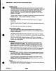
PARTS LISTING / Clear-Com CS-222 2-Channel Main Station SECTION 5 / Parts List for CS-222 2-CHANNEL INTERCOM STATION CC aF A Descritiaon X1.
r--------~ ~ ~ - -Lf ~~----- IL1 - ---AA as ~~~~~~~~~~~~~~------ ---- --------- gS ---- ---- t O' ark Y - ---- fV --- - i i CH 2iS 9 0 >-- N T U;~~~~~~~~~ WN' HW ~~~~~~~~~~~~~~~~~~~~~~~~~~~~~~~~~~~~~~~~~~~C |Lady,,. s4S¢1,,4~~~~~~~~ 8 p| $ t ; S~~a vp os BS tYX__ |~~~d i~~~~~~~~~~~~~~~~~~~~~~~~~~~~~~H s, of~~~~~~~~~~ _ >0- .