OPERATING MANUAL SRX 2150/128x1 SWITCHING SYSTEM US PATENTS 4,935,709 AND 5,481,073
This page intentionally left blank
Quintech Electronics and Communications Inc. SRX Series Switching System PAGE 1.0 INTRODUCTION............................................................................................................................1 2.0 MODULES .......................................................................................................................................2 3.0 INSTALLATION.............................................................................................................................
Quintech Electronics and Communications Inc. SRX Series Switching System 4.2.2.2 Ethernet Configuration .......................................................................................13 Static IP Configuration .......................................................................................13 DHCP .................................................................................................................14 QEC Port # .......................................................................
Quintech Electronics and Communications Inc.
This page intentionally left blank
Quintech Electronics and Communications Inc. SRX Series Switching System Rev. A 1.0 INTRODUCTION Thank you for purchasing an SRX Expandable Routing Switch. Quintech’s SRX series switches are based on the same technology as our popular SRM Series Modular Programmable RF Switches. They were developed to address the increasing need for expandable RF switching in telecommunication network signal processing centers and are equally suitable for audio/video, baseband, data, IF, and RF switching requirements.
Quintech Electronics and Communications Inc. SRX Series Switching System Rev. A 2.0 MODULES Two types of modules are used to configure an SRX system: an MCP 128 (8x1) controller and a 16x1 switching module. Every SRX system is comprised of one controller and 1 or more switching modules. A minimal SRX switching system consists of a single controller and one switching module.
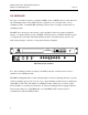
Quintech Electronics and Communications Inc. SRX Series Switching System Rev. A -5V +5V ELECTRONICS AND COMMUNICATIONS INC. C O N T R O L I N C O N T R O L O U T 1 2 3 4 5 6 7 8 9 10 11 12 13 14 15 16 OUTPUT INPUTS 16x1 Switching Module 3.0 INSTALLATION The SRX is very easy to install. Each module is 1RU (1.75”) in height and is easily installed in any standard rack, using four screws.
Quintech Electronics and Communications Inc. SRX Series Switching System Rev. A If you are using a computer to control the SRX, you can use a direct serial connection or a 10BaseT Ethernet connection. For serial control, connect a serial cable (RS-232 or RS-422/485) from the computer to the 9-pin SERIAL port on the rear panel of the controller module. The connector is shared for both RS-232 and RS-422/485. No NULL MODEM or crossover cable is needed when connecting an RS-232 cable.
Quintech Electronics and Communications Inc. SRX Series Switching System Rev. A 4.0 OPERATION The SRX Series Matrix Switching System can be controlled locally via the front panel keypad/LCD screen or remotely through the serial port or Ethernet port on the rear panel using the software provided with all standard SRX modules. If desired, all three methods can be used simultaneously. Firmware updates can be downloaded via the Serial and Ethernet ports.
Quintech Electronics and Communications Inc. SRX Series Switching System Rev. A To view the status of an output or input channel, type in the output/input number or use the scroll arrows to scroll up or down respectively. One, two, or three digits may be typed. For example, Output 1 may be represented as 1, 01, or 001. The number will be entered automatically about 1 second after no more digits are entered.
Quintech Electronics and Communications Inc. SRX Series Switching System 4.2 Rev. A Configuring System Options From the Main Menu, press 2 to access the System Options Menu. The System Options Menu enables you to set and modify basic configuration parameters. It also enables you to configure the SRX’s communications interface. 1. Configuration 2. Interface Options F4=Exit System Options Menu Pressing 1 will display the Configuration Menu.
Quintech Electronics and Communications Inc. SRX Series Switching System 4.2.1.1 Rev. A Setting Up the System The system configuration parameters consist of the SRX size and model number. The configuration settings are set at the factory and should not be changed unless directed by Quintech. Altering the configuration can prevent the SRX from operating correctly. 1. Matrix Size 3. Module Sizes 2.
Quintech Electronics and Communications Inc. SRX Series Switching System Rev. A Model The model number is included as part of the system’s firmware identification in accordance with the protocol outlined in Appendix A. The control system is not affected by the model number. System expansion requires no change of the model number.
Quintech Electronics and Communications Inc. SRX Series Switching System 4.2.1.2 Rev. A Upgrading the SRX’s Firmware Pressing 2 from the Configuration Menu displays the Load Firmware Screen. The Load Firmware Screen enables you to upgrade the internal firmware level of the SRX unit. Pressing F1 will put the controller in a special firmware download mode. The new firmware can then be downloaded via the serial port. This process requires the Rabbit Field Utility (RFU) v 2.
Quintech Electronics and Communications Inc. SRX Series Switching System Rev. A 4.2.2.1 Serial Configuration Whenever “Serial” is selected, you will be able to configure both the address of the SRX and the type of serial interface (RS-232, RS-485, or RS-422). 1. Address 3. Terminate RS485 2. Mode F4=Exit Address Menu Address The Address Screen allows you to set a 2-byte hexadecimal address for the switch. Addresses can be set from 00 to FF hexadecimal.
Quintech Electronics and Communications Inc. SRX Series Switching System Rev. A Mode The Mode Screen enables you to specify whether an RS-232, RS-485, or RS-422 serial interface will be used to control the serial communications. Mode: RS232 2=RS485 1=RS232 F4=Exit 3=RS422 Mode Screen Terminate RS485 The Terminate RS485 Screen allows you to enable or disable termination on the serial port. Only one device at the end of an RS485 cable should have termination enabled. 1.
Quintech Electronics and Communications Inc. SRX Series Switching System Rev. A 4.2.2.2 Etheret Configuration The Ethernet configuration screen controls the static IP configuration for Telnet (port 23) and the auxiliary QEC port. The QEC port allows you to send STX/ETX formatted packets to the SRX. Whenever “Ethernet” is selected in the Interface Options menu, you will be able to set the IP configuration (option 1), enable/disable the DHCP server (option 2), and configure the Ethernet port (option 3).
Quintech Electronics and Communications Inc. SRX Series Switching System Rev. A DHCP The DHCP Screen enables you to enable or disable the use of a DHCP server for obtaining IP address information. When set to ON, the IP address of the SRX is dynamically assigned by the DHCP server. Note that the IP address assigned in this manner will override any IP address that may have been specified via the IP Configuration Screen.
Quintech Electronics and Communications Inc. SRX Series Switching System Rev. A Password The Password Screen enables you to reset the QEC port access password to the Quintechspecified default. Press F4 to exit or F1 to reset the password. Reset password F1=Enter to “Quintech” F4=Exit Password Screen 4.3 Ethernet Control The SRX has a 10BaseT Ethernet port and supports TCP/IP. All commands are sent to the configured IP address and port.
Quintech Electronics and Communications Inc. SRX Series Switching System 4.4 Rev. A Serial Port Control The SRX has a standard DB-9 serial input connector on the back panel. This connector is shared for both RS-232 and RS-422/485 interfaces. The serial port parameters are fixed at 9600 baud, 8 data bits, no parity, and 1 stop bit (8N1). No NULL MODEM or crossover cable is required on this port. The command protocol for controlling the switch is provided in Appendix A.
Quintech Electronics and Communications Inc. SRX Series Switching System Rev. A 5.0 Troubleshooting This section has been written to help eliminate operator error. It does not describe how to repair damaged equipment. The control connections are properly connected, yet the system is not communicating. It is possible that the system needs to be biased or terminated. Refer to Appendix A. The front panel LED/LCD is not lit. This indicates the unit is not receiving power.
Quintech Electronics and Communications Inc. SRX Series Switching System Rev. A The SRX will not respond to protocol commands on the Serial Port. Make sure that the address in the commands being sent matches the serial address set for the SRX. Check that the serial interface mode (RS-232 or RS-485) is correct and that the serial cable from the computer is connected to the CONTROL IN DB-9 connector port on the back panel.
Quintech Electronics and Communications Inc. SRX Series Switching System Rev. A I am a qualified technician and would like to try to fix a problem myself. A warranty covers all units. QEC, or a representative of QEC, should make the required repairs. Removing any part of the chassis will void the warranty. Additionally, attempting to repair a unit could be dangerous. There is a lot of crosstalk between the signals. It may be necessary to “balance” your signal levels.
This page intentionally left blank
I N C O N T R O L O U T C O N T R O L O U T C O N T R O L 1 2 3 4 6 2 7 3 5 9 INPUTS 8 INPUTS 4 7 6 10 6 2 1 11 7 8 3 8 12 9 4 THE REPRODUCTION, USE OR DISCLOSURE, IN WHOLE OR 5 1 IN PART, OF THE DESIGN OR DETAILS CONTAINED HEREIN IS PROHIBITED WITHOUT THE WRITTEN PERMISSION OF QUINTECH, INC. THIS DRAWING IS THE PROPERTY OF QUINTECH, INC. AND TRANSMITTED IN CONFIDENCE. I N C O N T R O L ELECTRONICS AND COMMUNICATIONS INC.
This page intentionally left blank
AUTORANGING 100-240 VAC 50/60 Hz 2 AMP C O N T R O L C O N T R O L ETHERNET INPUTS O U T I N 1 2 3 4 1 OF 1 A 9/29/03 PAGE DR. BY: CK. BY: REV PHOTO NO. SCALE NTS A SIZE RF OUTPUT SRX RF & CONTROL CONNNECTIONS INDIANA, PENNSYLVANIA 15701 INFORMATION HEREIN IS PROPRIETARY TO: QUINTECH ELECTRONICS AND COMMUNICATIONS INC. CONTROL INTERCONNECTIONS RF MODULE INTERCONNECTIONS COMPUTER CONTROL CONNECTIONS RF OUTPUT C.O.
This page intentionally left blank
SRX 2150 Modular L-Band RF Routing Switch General Description: Quintech's SRX 2150 is a routing switch that is ideal for monitoring applications. Spanning a frequency range of 9502150 MHz, the system can be expanded in 16x1 modules up to a maximum configuration of 128x1. The SRX 2150 system greatly enhances system reliability by eliminating the need for patch panels and repetitive mechanical connections.
This page intentionally left blank
Quintech Electronics and Communications Inc. SRX Series Protocol Protocol Version 2.15 1 Quintech SRX Series Protocol v2.15 8/18/2003 Rev A This document specifies a common command protocol that can be used to control a Quintech SRX controller from a computer. Command Summary This list gives the commands defined in Protocol 2.15. C Check Change Flag / Unit Status. This flag will be set if a crosspoint has been changed since the last polling or if any alarms are present. E Ethernet.
Quintech Electronics and Communications Inc. SRX Series Protocol Protocol Version 2.15 2 Protocol Message Structure Commands packets can be sent over the Ethernet and serial ports (if available) and use a standard STX/ETX protocol wrapper. Each packet includes a header byte, a two-byte address field, a command byte, necessary data bytes, end byte, and a checksum byte. The bytes are transmitted using an 8-bit word, with 1 stop bit and no parity.
Quintech Electronics and Communications Inc. SRX Series Protocol Protocol Version 2.15 3 Address FF is a serial broadcast address. Any unit will respond to a command with an address of FF regardless of the actual serial address set for the unit. Commands being sent to units over Ethernet must contain an address of FF for proper operation. Otherwise a nonmatching serial address could cause the command to be rejected even though the IP address was correct.
Quintech Electronics and Communications Inc. SRX Series Protocol Protocol Version 2.15 4 Command Descriptions C: Check Change Flag/Unit Status The change flag tells the user if any crosspoint changes are in the queue. The queue will store up to eight changes made from the local front panel keypad control. This command can be sent periodically to check if any local changes have been made or if any alarms have occurred. The change flag is cleared only when the queue is empty.
Quintech Electronics and Communications Inc. SRX Series Protocol Protocol Version 2.15 5 EG: Set Ethernet Default Gateway This command sets the default Ethernet gateway. Command format: 02 XX XX 45 STX ADR ADR E 47 G XX nn XX nn XX nn XX nn XX nn XX nn XX nn 03 XX ETX CHK 30 0 31 1 30 0 XX nn XX nn 2E . 2E . XX nn XX nn XX nn 2E . 30 0 30 0 30 0 2E . Example Command: 02 46 STX F 46 F 45 E 47 G 2E . 30 30 30 2E 30 30 31 03 2D 0 0 0 . 0 0 1 ETX CHK (Set Gateway = 010.000.000.
Quintech Electronics and Communications Inc. SRX Series Protocol Protocol Version 2.15 6 EI: Set Ethernet IP Address This command sets the Ethernet IP Address. Command format: 02 XX XX 45 STX ADR ADR E 49 I XX nn XX nn XX nn XX nn XX nn XX nn XX nn 03 XX ETX CHK 30 0 31 1 30 0 XX nn XX nn 2E . 2E . XX nn XX nn XX nn 2E . 30 0 30 0 30 0 2E . Example Command: 02 46 STX F 46 F 45 E 49 I 2E . 30 30 30 2E 32 33 34 03 27 0 0 0 . 2 3 4 ETX CHK (Set IP Address = 010.000.000.
Quintech Electronics and Communications Inc. SRX Series Protocol Protocol Version 2.15 7 ELD: Ethernet Lock Disable This command disables the Ethernet lock. If the lock has been enabled (using the ELE command), command packets input from the Ethernet port are received but ignored except for the ELD command. This provides an additional level of control over the switch and the Ethernet port. The ELD command is used to disable the lock and enable the processing of command packets.
Quintech Electronics and Communications Inc. SRX Series Protocol Protocol Version 2.15 8 ELE: Ethernet Lock Enable This command enables the Ethernet command lock. When the lock is enabled, command packets input from the Ethernet port are received but ignored except for the ELD command. The ELD command is used to disable the lock and enable the processing of command packets.
Quintech Electronics and Communications Inc. SRX Series Protocol Protocol Version 2.15 9 ELP: Set Ethernet Lock Password This command sets a new Ethernet Lock Password. The password is an alpha-numeric value from 1 to 10 characters. A null password (no password) is also allowed.
Quintech Electronics and Communications Inc. SRX Series Protocol Protocol Version 2.15 10 EP: Set Ethernet Port This command sets the Ethernet port that is monitored for command packets. The default port set at the factory is 9100. There is no need to change this unless it conflicts with another network device.
Quintech Electronics and Communications Inc. SRX Series Protocol Protocol Version 2.15 11 ES: Set Ethernet Subnet Mask This command sets the Ethernet Subnet Mask. Command format: 02 XX XX 45 STX ADR ADR E 53 S XX nn XX nn XX nn XX nn XX nn XX nn XX nn 03 XX ETX CHK 32 2 35 5 35 5 XX nn XX nn 2E . 2E . XX nn XX nn XX nn 2E . 32 2 35 5 35 5 2E . Example Command: 02 46 STX F 46 F 45 E 53 S 2E . 32 35 35 2E 32 33 34 03 3B 2 5 5 . 0 0 0 ETX CHK (Set Netmask = 255.255.255.
Quintech Electronics and Communications Inc. SRX Series Protocol Protocol Version 2.15 12 F: Firmware Version / Unit ID This command will return a message with the protocol and firmware versions, the series and model number, and the size of the matrix. The fields will be returned as follows: “Firmware version” “Protocol version” “Model Number”/ “Matrix Size”. For example, a 16x1 SRX would give a response of the form “Fv1.01 Pv2.15 SRX2150/016X001”.
Quintech Electronics and Communications Inc. SRX Series Protocol Protocol Version 2.15 13 L: Lock Crosspoint This command sets a crosspoint and then “locks” it so that output may not be rerouted to any other input until it is either unlocked or locked again to a different output. A locked crosspoint may be rerouted by locking it to another crosspoint. A lock can be over-ridden from the front panel.
Quintech Electronics and Communications Inc. SRX Series Protocol Protocol Version 2.15 O: Query Output Channel This command queries for the input connected to the specified output. Example command sent: 02 XX XX 4F 30 30 31 03 XX STX ADR ADR O 0 0 1 ETX CHK (Query the status of output 1) Example positive response: 06 XX XX 4F 30 30 32 03 XX ACK ADR ADR O 0 0 2 ETX CHK (Output 1 is connected to input 2) DESIGNS AND SPECIFICATIONS SUBJECT TO CHANGE WITHOUT NOTICE 2002 QUINTECH INC. ALL RIGHTS RESERVED.
Quintech Electronics and Communications Inc. SRX Series Protocol Protocol Version 2.15 15 Q: Check Queue This command will read the change queue. The change queue contains up to 8 crosspoint changes executed since the last Q command. All crosspoint changes are put in the queue regardless of the source. If more than one change is executed for a given output, only the last change will be stored in the queue.
Quintech Electronics and Communications Inc. SRX Series Protocol Protocol Version 2.15 16 S: Set Crosspoint This command will connect one input to an output. The command byte is followed by three bytes giving the output, then three bytes giving the input. The output must be 001 for an SRX.
Quintech Electronics and Communications Inc. SRX Series Protocol Protocol Version 2.15 U: Unlock Crosspoint This command will unlock a locked crosspoint. Command sent: 02 XX XX 55 30 30 31 30 STX ADR ADR U 0 0 1 0 (Unlock output 1 to input 5) 30 0 35 5 03 XX ETX CHK Positive response sent: 06 XX XX 55 ACK ADR ADR U 03 XX ETX CHK DESIGNS AND SPECIFICATIONS SUBJECT TO CHANGE WITHOUT NOTICE 2002 QUINTECH INC. ALL RIGHTS RESERVED.
Quintech Electronics and Communications Inc. SRX Series Protocol Protocol Version 2.15 18 Negative Responses: Occasionally, the matrix will be unable to carry out a command due to various reasons. The NAK reply set is provided to help determine where the error occurred. A NAK reply will be sent after the matrix has received the CHK byte. x: Checksum Incorrect This reply is sent when the checksum sent by the computer controller is different from the one calculated by the matrix controller.
Quintech Electronics and Communications Inc. SRX Series Protocol Protocol Version 2.15 19 i: Improper Data This reply is sent if an improper number of data bytes are contained in the protocol wrapper. For example, if an “S” command is sent with only an output number and no input number. This error will also be sent for any command that contains too many or too few bytes, even if the command does not have any data bytes.
Quintech Electronics and Communications Inc. SRX Series Protocol Protocol Version 2.15 20 Serial Interface A new command can be sent to the matrix as soon as a response to the previous command is received. If a break in communication occurs while a message is being transmitted the input buffer will automatically clear and no error response will be given. Serial Parameters: Baud Rate: Data Bits: Stop Bits: Parity: Protocol: Flow Control: 9600 8 1 None STX/ETX None.
Quintech Electronics and Communications Inc. SRX Series Switching System Rev. A NECESSARY EQUIPMENT x Hewlett Packard Network Analyzer – Models 8714C (75 ȍ), 8714ET (50 ȍ), or equivalent x 75 ȍ coaxial cables (N – to – N type), 50 ȍ if using the 8714ET x Connectors and adapters CALIBRATION & SETTINGS 1. Turn on the Network Analyzer and allow it to complete its warm-up procedure. 2. Set the frequency to correspond to your system. 3. Select Channel 1 as Transmission and Channel 2 as Reflection. 4.
This page intentionally left blank
IN PART, OF THE DESIGN OR DETAILS CONTAINED HEREIN IS PROHIBITED WITHOUT THE WRITTEN PERMISSION OF QUINTECH, INC. CK. BY: TOM LONG NTS 06/05/03 DWG NO. TYPICAL TEST SETUP A REV 1 OF 1 PAGE INDIANA, PENNSYLVANIA 15701 QUINTECH ELECTRONICS AND COMMUNICATIONS INC. SCALE DR. BY: A SIZE C.O.
This page intentionally left blank
Setting the SRX Expansion Module Address Switches Each SRX expansion switch module has two internal rotary switches that are used to set the address for that unit. Each unit in a switch matrix only responds to control commands prefaced with an address that corresponds to the address set on the switches. The address for a particular unit is pre-set at the factory and normally will never need to be changed.
This page intentionally left blank
Quintech Electronics and Communications Inc.
This page intentionally left blank