
Service manual


Assembly Tests
Electronic Tests
9
Rev. 01 Model 515B/C
Service Manual
39
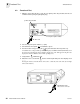
3. Press to turn the monitor on.
4. Monitor pin 6 of IC19, check for sync pulses. Check that the pulse amplitude is above
50mv (best to AC couple the oscilloscope).
5. Verify the following voltages, use TP16 AGND as reference:
*These voltages are based on the +VA supply value with the listed tolerance.
6. Situate the keypanel so as to gain easy access to the keys without stressing the ribbon
cable. Check that finger sensor icon is illuminated (probe not connected).
7. Connect the TB500B. Set as follows:
8. Verify a Pulse Rate of 59-61 and Saturation value of 90-94. Finger sensor and hand
icons should be off.
9. Adjust pulse beep volume using up/down arrows on keypanel. Verify the volume
increases and decreases.
10. Set TB500B SATURATION to 62, verify the alert bar flashes and alarm tone sounds.
Press , verify the alert tone mutes and the icon flashes.
11. Set TB500B SATURATION to 92, verify Saturation display updates and alert bar stops
flashing.
12. Press and hold the button until the LED illuminates.
13. Verify the following SpO
2
values on the monitor for each of the SIGNAL ATTENUATION
and SATURATION settings on the TB500B Sensor Simulator. Note that the pulse rate
should remain stable at 50-61 beats per minute.
TP1 VDD +4.90 - 5.10 VDC
TP4 -V5 -4.88 - (-)5.12 VDC
TP11 +VA +8.88 - 9.22 VDC
TP10 -VA* negative value of +VA w/-550mv tolerance
TP12 LEDSRC* positive value of +VA w/-2.5 volt tolerance
(no sensor connected)
TP13 LEDPWR +8.88 - 9.22 VDC (no sensor connected)
TP3 VREF2.5 +2.5 VDC (1mv tolerance)
SENSOR TYPE: 87XX
POWER ON: ON
ATTENUATION: 3
SATURATION: 92
SAT.
SETTING
SIGNAL
ATTEN.
Monitor’s SpO
2
display
TB500A TB500B
100 3 98-100 98-100
92 3 90-94 90-94
82 3 82-86 80-84
72 3 75-79 70-74