
Service manual


Accuracy Test
Electronic Tests
9
Rev. 01 Model 515B/C
Service Manual
41
Verify all the LEDs and segments briefly illuminate.
The software revision level will appear in the SpO
2
display, the model number “515” will
appear in the pulse rate display.
4. Verify the is flashing and the SpO
2
and pulse rate windows display “- - -”.
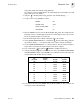
5. Set the controls on the TB500B as follows:
6. Plug the TB500B connector into the Model 515B/C SpO
2
input. Check that the pulse
bar begins to pulse, and that SpO
2
and pulse rate values appear after a few seconds.
Check for a plethysmogram on model 515C.
7. Check that the SpO
2
value is 90-94, and that the pulse rate is 59-61.
8. Set the SIGNAL ATTENUATION to 1, verify that the flashes and the SpO
2
and pulse
rate windows display “- - -.” An alarm should sound, and the alert bar should flash.
9. Set the SIGNAL ATTENUATION to 3, verify the alarm is silenced and the alert bar no
longer flashes. Check that the SpO
2
and pulse rate values reappear.
10. Press and hold the key until the illuminates (audible alert silence).
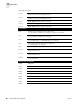
11. Verify the following SpO
2
values on the monitor for each of the SIGNAL ATTENUATION
and SATURATION settings on the TB500B Sensor Simulator. Note that the pulse rate
should remain stable at 50-61 beats per minute.
12. Turn off then disconnect the TB500B. Turn the Model 515B/C off. This completes the
accuracy test for the Model 515B/C.
POWER: ON
SENSOR TYPE: 87XX
SIGNAL ATTENUATION: 3
SATURATION: 92
SAT.
SETTING
SIGNAL
ATTEN.
Monitor’s SpO
2
display
TB500A TB500B
100 3 98-100 98-100
92 3 90-94 90-94
82 3 82-86 80-84
72 3 75-79 70-74
62 3 67-71 60-64
62 7 N/A N/A
72 7 74-80 68-76
82 7 80-88 78-86
92 7 88-96 88-96
100 7 98-100 98-100