
User manual


8
© 2002 Directed Electronics, Inc
1
2
4
3
5
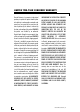
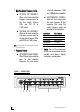
FIGURE 1—CONTROL PANEL
5.
HHiigghh-PPaassss OOuuttppuutt FFrreeqquueennccyy CCoonnttrrooll
IN/FRONT OUT FREQUENCY:
When in this knob controls the
high-pass crossover point for
the front outputs between
30Hz and 400 Hz at
12dB/octave.
OUT/REAR OUT FREQUENCY:
When out this knob controls the
high pass crossover point for
the rear outputs between 30Hz
and 400 Hz at 12dB/octave.
NNOOTTEE::
If rear panel switch #7 is in the full range position this
knob has no function.
6.
FFrreeqquueennccyy CCoonnttrroollss
IN/FREQUENCY GAIN CONTROL:
When IN these knobs control the
gains for their respective
frequencies. The center position
is flat with a maximum +18dB
and -18dB adjustment capability.
OUT/PARAMETER CONTROLS:
When out these knobs control
the center frequency of their
respective filter band. The
center frequency ranges are
described in the chart below.
CCoonnttrrooll KKnnoobb FFiilltteerr PPaarraammeetteerr
Subwoofer 30 to 70 Hz
Midbass 125 to 250 Hz
Low Midrange 400 to 800 Hz
High Midrange 1 to 5 kHz
High Frequencies 8 to 20 kHz
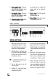
7.
AAuuxx IInn
- This is a 3.5 mm stereo input
jack for use as an auxiliary input for
portable music players, laptops,
camcorders, or video games.
6
7