
User manual


9
© 2002 Directed Electronics, Inc
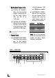
Power Connector
1.
RReemmoottee TTuurrnn OOnn OOuuttppuutt
- This
output is intended to be the remote
turn on for the system amplifiers
and has a built-in delay. Two to
three seconds after the 6500
receives a (+)12V turn on signal it
will send a (+)12V turn on signal
to the amplifiers. This feature is
designed into the 6500 to elimi-
nate system turn-on pops that can
occur when several components
turn on at the same time.
2.
((++))1122VV CCoonnssttaanntt PPoowweerr
- This is
the main power input for the 6500
and must be connected to a
(+)12V constant power supply. DO
NOT connect this to a switched 12V
source or the system may pop
when the key is turned off.
3.
RReemmoottee TTuurrnn OOnn IInnppuutt
- This is the
input for turning on the 6500 and
system amplifiers. It should be
connected to the (+) 12V remote
turn on output of the system head
unit. The 6500 has a built in turn
off delay to prevent turn-off pops.
When the remote turn on signal
from the head unit shuts off, the
amplifiers will turn off immediately
and the 6500 will stay on for five
seconds before turning off. This
feature is designed into the 6500
to eliminate system turn off pops
that can occur when several compo-
nents turn off at the same time. DO
NOT connect this to a (+)12V
constant power supply.
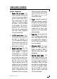
4.
GGrroouunndd
- Connect this terminal to a
quality ground location, preferably
the chassis of the head unit, which
must itself be properly grounded to
the vehicle chassis. It is not recom-
mended that the factory radio
ground be used for after market
audio components.
5.
PPoowweerr FFuussee
- This fuse protects the
6500's on-board electrical compo-
nents. Never replace this fuse with
one of higher value or damage to
the 6500 could occur and result in
loss of your warranty.
6.
IIlllluummiinnaattiioonn SSwwiittcchh
- This switch
changes the front panel back-
lighting from BLUE to GREEN to
match the vehicle dash or radio
backlighting.
7.
HHiigghh PPaassss OOuuttppuutt SSwwiittcchh
- This
switch controls whether the front
and rear outputs are full range or
crossed over as high pass outputs to
the amplifiers. When set to high
pass output the front and rear output
crossovers are separately variable
from 30 to 400Hz, by using the
high pass frequency control knob
(#5) on the front panel.
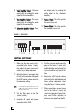
REAR PANEL FEATURES