Model 200 Installation Guide ® © 2001 Directed Electronics, Inc. Vista, CA N122 3-01 Rev. B 1.
table of contents What Is Included . . . . . . . . . . . . . . . . . . . . . 3 Plug-In LED and Valet/Program Switch . . . . . . 15 Installation Points to Remember . . . . . . . . . . 4 On-Board Doubleguard Shock Sensor . . . . . . . 15 Deciding on Component Locations Siren . . . . . . . . . . . . . . . . . . Control Module. . . . . . . . . . . . Valet/Program Switch . . . . . . . Status LED . . . . . . . . . . . . . . . . . . . . . . . . . . . . . . . . . . . . . . . . . . . . . . . . . . . . .
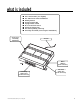
what is included ■ ■ ■ ■ ■ ■ ■ ■ ■ The control module (see diagram) Two 470T Series remote transmitters Primary harness A plug-in status LED A plug-in Valet® switch An on-board shock sensor A back-up battery siren Two back-up battery siren keys A mercury tilt switch (for motorcycle installations) Shock Sensor Sensitivity Adjustment Antenna White LED Port (2-Pin Connector) H1 Primary Harness Port (14-Pin Connector) © 2001 Directed Electronics, Inc.
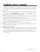
installation points to remember This system has many unique features, some of which require unique testing procedures! Carefully review both this installation guide and the owner’s guide before beginning the installation or this system, particularly the wiring diagrams. ■ The control module’s PC board is protected with a conformal coating which will combat condensation buildup, however the system is NOT WATERPROOF.
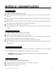
deciding on component locations locations for the siren Some things to remember when mounting the siren: ■ Mount the siren with screws, taking care that the screws do not come in contact with any wire harnesses or fluid lines. ■ Keep it away from heat sources. Radiators, exhaust manifolds, turbochargers, and heat shields are all locations to avoid. ■ Mount it where a thief cannot easily disconnect it. Both the siren and its wires should be difficult to find.
finding the wires you need Now that you have decided where each component will be located, you’re going to find the wires in the vehicle that the security system will be connected to. IMPORTANT! Do not use a 12V test light to find these wires! Use a digital multimeter for all testing. obtaining constant 12V We recommend two possible sources for 12V constant: the (+) terminal of the battery, or the constant supply to the ignition switch. Always install a fuse within 12 inches of this connection.
4. Turn the ignition key switch to the run position. If your meter reads (+)12V, go to the next step. If it doesn’t, probe another wire. 5. Now turn the key to the start position. The meter display should stay steady, not dropping by more than a few tenths of a volt. If it drops close to or all the way to zero, go back to Step 3. If it stays steady at (+)12V, you have located an ignition wire.
making your wiring connections Before making your connections, plan how your wires will be routed. For instance, the red 12V constant input and the orange ground-when-armed output (for the starter kill relay) will often be routed together to the ignition switch harness. In order to keep the wiring neat and make it harder for a thief to find, you may wish to wrap these wires together in electrical tape or conceal them in tubing similar to what the manufacturer used.
primary harness (H1), 14-pin connector H1/1 H1/2 H1/3 H1/4 H1/5 H1/6 H1/7 H1/8 H1/9 H1/10 H1/11 H1/12 ______ ______ ______ ______ ______ ______ ______ ______ ______ ______ ______ ______ GREEN (-) CLOSED LOOP BLACK (-) BATTERY GROUND LIGHT GREEN/BLACK ORANGE BLUE (-) OPTIONAL MULTIPLEXED SENSOR INPUT (-) GROUND-WHEN-ARMED 500 mA OUTPUT (-) INSTANT TRIGGER/MERCURY TILT SWITCH INPUT WHITE RED (+) LIGHT FLASH OUTPUT #1 (+) 12V CONSTANT POWER YELLOW (+) IGNITION INPUT BROWN (-) SIREN OUTPUT BLACK
primary harness wire connection guide H1/1 GREEN (-) closed loop This wire can be used to protect a part of the vehicle where a trigger is desired when the wires of the connection are not in contact, rather than in contact. This closed loop connection is useful for protecting things such as saddlebags, luggage carriers, etc. that could be easily removed from a motorcycle or other recreational vehicle. Connect this wire through the object being protected and then to the battery ground loop.
H1/5 BLUE (-) instant trigger/mercury tilt switch input (for motorcycle installations) Connect this wire to one of the mercury tilt switches’ wires. Connect the other tilt switch wire to battery ground. (These wires are interchangeable.) The mercury should only bridge the contacts if the motorcycle is tilted off its stand. A negative (-) input to this wire will cause an instant trigger, which will report on Zone 1.
H1/8 YELLOW (+) ignition input Connect this wire to an ignition wire as described in the Finding the Wires You Need section of this manual. This wire must show (+)12V with the key in the run position and during cranking. Make sure that this wire cannot be shorted to the chassis at any point. H1/9 BROWN (-) siren output The siren should be mounted away from excessive heat sources, such as the exhaust manifold. Connect the H1/9 wire to the brown wire of the siren.
H1/12 RED/WHITE channel 2, 200mA (-) output When the system receives the code controlling Channel 2 for longer than 1.5 seconds, the red/white wire will supply an output as long as the transmission continues. This can be used to operate an optional relay-driven function. IMPORTANT! Never use this wire to drive anything but a relay or a low-current input! The transistorized output can only supply 200 mA of current. Connecting directly to a solenoid, motor, or other high-current device will cause it to fail.
making siren connections Instructions for connecting the siren wires are described below. RED (+)12V constant Connect this wire to a fused source of constant 12V. Be sure to connect this wire to a source capable of handling the required current draw, such as the vehicle battery. BLACK (-) chassis ground Connect this wire to the (-) ground terminal of the vehicle battery. BROWN (-) siren input Connect this wire to the (-) brown siren output of the security system.
plug-in LED and valet/program switch These plug into the module. The Status LED plugs into the white two-pin socket, while the Valet®/Program switch should be plugged into the blue two-pin socket. The Status LED and the Valet/Program switch each fit into a /32-inch hole. 9 Status LED Valet®/Program Switch on-board doubleguard shock sensor There is a Doubleguard® shock sensor inside the control unit. Adjustments are made via the rotary control as indicated above.
transmitter/receiver learn routine The system comes with two transmitters that must be “taught” to the receiver. Use the following learn routine to program the transmitters, add transmitters to the system or to change button assignments if desired. IMPORTANT! All remotes that will be used with the system must be programmed at the same time. Each time the learn routine is accessed and a remote is successfully learned by the system, any other remotes that had previously been programmed will be erased. 1.
system features learn routine The System Features Learn Routine™ dictates how the unit operates. It is possible to access and change any of the feature settings using the Valet®/Program switch. 1. Ignition: Turn the ignition on, then back off. (The H1/9 YELLOW wire must be connected.) 2. Select a feature: Press and release the Valet®/Program button the number of times corresponding to the feature you wish to change.
To exit the System Features Learn Routine, do one of the following: ■ Turn the ignition on. ■ No activity for longer than 15 seconds. ■ Press the Valet/Program switch too many times.
6 CHANNEL 3 INSTANT/LATCHED/LATCHED RESET WITH IGNITION/30-SECOND TIMED/60-SECOND TIMED/90SECOND TIMED: Channel 3 can be programmed for these output configurations. The unit is set to the default instant output. To change the configuration, use to toggle to the different settings. 7 DISARM PULSE COUNT 1 to 5 PULSES: This feature allows you to program the number of pulses used to manually disarm the system using the Valet button. The factory default setting is one pulse.
nuisance prevention circuitry Nuisance Prevention® Circuitry (NPC®) is designed to prevent repeating triggers, such as those from an out-of-adjustment sensor or temporary environmental conditions. If NPC detects the same zone triggering three times, and these three triggers are within an hour of each other, that zone will be bypassed for sixty minutes.
table of zones When using the Diagnostic functions, use the Table of Zones to see which input has triggered the system. The status LED will. It is also helpful in deciding which input to use when connecting optional sensors and switches. ZONE NO.
The siren sounds weak or garbled: ■ Check all the grounding points, including the siren ground and alarm ground. ■ Check the alarm for 12V output on the H1/9 BROWN wire. ■ For all motorcycle and recreational vehicle installations, a direct battery ground is recommended. The starter kill does not work: ■ Does the H1/8 YELLOW wire test 12 volts during the crank or start cycle? If not, you may not have the true ignition wire.
notes © 2001 Directed Electronics, Inc.
© 2001 Directed Electronics, Inc.