
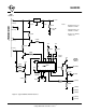
Specifications

Interpreting Trouble Codes
Likely the most common use that the ELM323 will
be put to is in obtaining the current Diagnostic Trouble
Codes or DTCs. Minimally, this requires that a mode
03 request be made, but first one should determine
how many trouble codes are presently stored. This is
done with a mode 01 PID 01 request as follows:
>01 01
To which a typical response might be:
41 01 81 07 65 04
The 41 01 signifies a response to the request, and
the next data byte (81) is the number of current trouble
codes. Clearly there would not be 81 (hex) or 129
(decimal) trouble codes present if the vehicle is at all
operational. In fact, this byte does double duty, with
the most significant bit being used to indicate that the
malfunction indicator lamp (MIL, or ‘Check Engine’)
has been turned on by one of this module’s codes (if
there are more than one), while the other 7 bits of this
byte provide the actual number of stored trouble
codes. In order to calculate the number of stored
codes when the MIL is on, then, subtract 128 (or 80
hex). When the result is less than 128, simply read the
number of stored codes directly.
The above response then indicates that there is
one stored code, and it was the one that set the Check
Engine Lamp or MIL on. The remaining bytes in the
response provide information on the types of tests
supported by that particular module (see the SAE
document J1979 for further information).
In this instance, there was only one line to the
response, but if there were codes stored in other
modules, they each could have provided a line of
response. To determine which module is reporting the
trouble code, one would have to turn the headers on
(AT H1) and then look at the third byte of the three
byte header for the address of the module that sent
the information.
Having determined the number of codes stored,
the next step is to request the actual trouble codes
with a mode 03 request:
>03
A response to this could be:
43 01 33 00 00 00 00
The ‘43’ in the above response simply indicates
that this is a response to a mode 03 request. The other
6 bytes in the response have to be read in pairs to
show the trouble codes (the above would be
interpreted as 0133, 0000, and 0000). Note that the
response has been padded with 00’s as required by
the SAE standard for this mode – the 0000’s do not
represent actual trouble codes.
As was the case when requesting the number of
stored codes, the most significant bits of each trouble
code also contain additional information. It is easiest to
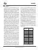
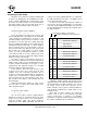
use the following table to interpret the extra bits in the
first digit as follows:
Powertrain Codes - SAE defined
0
“ “ - manufacturer defined
“ “ - SAE defined
“ “ - jointly defined
1
2
3
If the first hex digit received is this,
Replace it with these two characters
Chassis Codes - SAE defined
4
“ “ - reserved for future
5
6
7
Body Codes - SAE defined
8
9
A
B
Network Codes - SAE defined
C
D
E
F
P0
P1
P2
P3
C0
C1
C2
C3
B0
B1
B2
B3
U0
U1
U2
U3
“ “ - reserved for future
“ “ - manufacturer defined
“ “ - manufacturer defined
“ “ - manufacturer defined
“ “ - manufacturer defined
“ “ - manufacturer defined
“ “ - manufacturer defined
“ “ - reserved for future
Taking the example trouble code (0133), the first
digit (0) would then be replaced with P0, and the 0133
reported would become P0133 (which is the code for
an ‘oxygen sensor circuit slow response’). As for
further examples, if the response had been D016, the
code would be interpreted as U1016, while a 1131
would be P1131.
More than one ECU module can respond to
requests such as this, so be prepared to possibly
receive several lines of responses. To determine
which ECU is reporting each line would require turning
the headers on with the AT H1 command.
12 of 19ELM323DSD Elm Electronics – Circuits for the Hobbyist
< http://www.elmelectronics.com/ >
ELM323