
Specifications

Example Applications
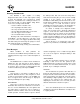
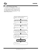
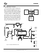
The SAE J1962 standard dictates that all OBD
compliant vehicles must provide a standard connector
near the driver’s seat, the shape and pinout of which is
shown in Figure 4 below. The circuitry described here
can be used to connect to this J1962 plug without
modification to your vehicle.
The male J1962 connector required to mate with a
vehicle’s connector may be difficult to obtain in some
locations, and you could be tempted to improvise by
making your own connections to the back of your
vehicle’s connector. If doing so, we recommend that
you do nothing that would compromise the integrity of
your vehicle’s OBD network. The use of any connector
which could easily short pins (such as an RJ11 type
telephone connector) is definitely not recommended.
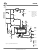
The circuit of Figure 5 on the next page shows
how the ELM323 could typically be used. Circuit power
is obtained from the vehicle (via OBD pins 16 and 5)
and, after some capacitive filtering, is presented to a
five volt regulator. (Note that a few vehicles have been
reported not to have a pin 5. On these, you use pin 4
instead of pin 5.) The regulator powers several points
in the circuit as well as an LED (for visual confirmation
that power is present).
The remaining two connections to the vehicle
(OBD pins 7 and 15) are for the two data lines
prescribed by the ISO 9141 and ISO 14230 standards.
To meet the standards, the ELM323 controls both lines
through the NPN transistors shown, with the pullup
resistors connected to their collectors. The 510Ω value
for these resistors is specified in the standards, and
substituting for a larger value would only increase rise
times, possibly making the circuit inoperable.
Reducing the value could cause circuit damage, so try
to keep as close as possible to the 510Ω. Note also
that 1/2W resistors should be used (and that 1/4W
240Ω + 270Ω resistors work well, too).
Data is received from the K Line of the OBD bus
and inverted by the PNP transistor shown before being
applied to pin 11 of the ELM323. This transistor raises
the threshold voltage to about 4V from the inherent
2.5V with the CMOS input of the ELM323. This helps
to increase noise immunity while reducing transition
times at the input pin, because of the amplification.
A very basic RS232 interface is shown connected
to pins 5 and 6 of the ELM323. This circuit ‘steals’
power from the host computer in order to provide a full
swing of the RS232 voltages without the need for a
negative supply. The RS232 pin connections shown
are for a standard 9 pin connector. If you are using the
older 25 pin style, please refer to the web site help
pages for the equivalent pins.
RS232 data from the computer is directly
connected to pin 5 of the ELM323 through a 47KΩ
current limiting resistor. This resistor allows for voltage
swings in excess of the supply levels while preventing
damage to the ELM323. A single 100KΩ resistor is
also shown in this circuit so that pin 5 is not left floating
if the computer is disconnected.
Transmission of RS232 data is via the PNP
transistor shown connected to pin 6. This transistor
allows the output voltage to swing between +5V and
the negative voltage stored on the 0.1µF capacitor
(which is charged by the computer’s TxD line). Using
the computer’s own supply guarantees that the RS232
voltage levels will be compatible. Note also that the
ELM323’s pin 4 has been tied to VDD, so that by
default linefeed characters will be sent whenever a
carriage return is sent.
The four LEDs shown (on pins 7 to 10) have been
provided as a visual means of confirming circuit
activity. Resistors are shared among Tx and Rx LEDs
as they will not be on at the same time (the ELM323 is
not capable of true multitasking). The OBD bus may
be in an initialization phase while data is being sent or
received on the RS232 bus, though, so separate
resistors are shown for these two groups.
Finally, the crystal shown connected between pins
2 and 3 is a common TV type that can be easily and
inexpensively obtained. The 27pF crystal loading
capacitors shown are typical only, and you may have
to select other values depending on what is specified
for the crystal you obtain.
This completes the description of Figure 5. While it
is the minimum required to talk to an OBD equipped
vehicle, it is a fully functional circuit. Page 19 shows
one more example circuit – that of an OBD monitor.
Figure 4. Vehicle Connector
81
9 16
17 of 19ELM323DSD Elm Electronics – Circuits for the Hobbyist
< http://www.elmelectronics.com/ >
ELM323