
Specifications

19 of 19ELM323DSD Elm Electronics – Circuits for the Hobbyist
< http://www.elmelectronics.com/ >
Example Applications (continued)
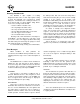
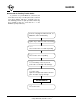
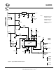
As a final example, we provide an OBD monitor.
There are times when it would be convenient to be
able to simply monitor the OBD bus for one reason or
another – personal learning, monitoring others in
teaching environments, and also there are apparently
some vehicles produced that continually send OBD
information, so can not be ‘read’ in the standard way.
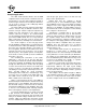
For these situations, a simplified version of the
circuit in Figure 5 can be used as shown in Figure 6
below. The K and L line bus transmit interfaces have
been removed as they are no longer required (and
would only serve to load the bus down). The simplified
three-wire interface is connected to the OBD bus as
shown at right, and an AT MA command is issued
(refer to the Monitoring the Bus section for more
information on that command). That’s all there is to it!
Figure 6. A Simplified OBD Monitor Circuit
+5V
3.58MHz
27pF
4.7KΩ
+5V
78L05
+5V
0.01µF
7
(K Line)
5
(Signal
Ground)
16
(Battery
Positive)
OBD
Interface
10KΩ
1
2
3
4
7
6
5
323
14
13
12
11
8
9
10
27pF
10KΩ
0.1µF
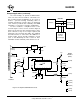
Vehicle Scan Tool
(as in Fig 5)
Monitor
Circuit
(as in Fig 6)
OBD Bus
ELM323
2 (RxD)
5 (SG)
3 (TxD)
47KΩ
100KΩ
0.1µF
RS232
Interface
(DB9F)
4.7KΩ
10KΩ
+5V
1 (DCD)
4 (DTR)
6 (DSR)
7 (RTS)
8 (CTS)