® Model 417 Installation Guide ® © 2000 Directed Electronics, Inc. Vista, CA N417A 9-00 Downloaded from: http://www.guardianalarms.
table of contents What Is Included . . . . . . . . . . . . . . . . . . . . . 3 Product Description . . . . . . . . . . . . . . . . . . . 4 Installation Points to Remember . . . . . . . . . . 4 Tools Required . . . . . . . . . . . . . . . . . . . . . . . 5 Deciding on Component Locations . . . . . . . . . Siren . . . . . . . . . . . . . . . . . . . . . . . . . . . Control Module . . . . . . . . . . . . . . . . . . . . Valet/Program Switch . . . . . . . . . . . . . . . . Status LED . . . . . . . . . . . . . .
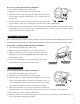
what is included ■ ■ ■ ■ ■ ■ ■ The control module (see diagram) A Revenger® Soft Chirp® siren The plug-in Valet®/program switch The plug-in status LED 12-Pin primary harness Starter kill relay package A Stinger® Doubleguard® shock sensor on-board the control module 12-Pin Primary Harness Port Shock Sensor Adjustment 2-Pin LED Port 2-Pin Blue Valet/Program Port © 2000 Directed Electronics, Inc.
product description This unit is used to enhance a vehicle’s original equipment from manufacturer (OEM) factory keyless entry system by converting it into a full-featured alarm system. It has been designed to work with the factory transmitters and to interface with minimal wiring to the vehicle. The databus interface module interfaces with the vehicle’s Class II databus signal wire to arm and disarm the vehicle, and to determine if there has been a vehicle intrusion.
AFTER THE INSTALLATION ■ Test all functions. The “Using Your System” section of the Owner’s Guide is very helpful when testing. ■ When testing, don’t forget that this system is equipped with Nuisance Prevention Circuitry (NPC). This circuitry can bypass both instant trigger zones, making them appear to stop working. ■ Carefully reassemble the under-dash trim panels. ■ Inspect the engine compartment for tools that may have been left behind.
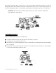
■ Point the siren down so water does not collect in it. locations for the control module ■ Never put the control module in the engine compartment! ■ The first step in hot-wiring a vehicle is removing the driver's side underdash panel to access the starter and ignition wires. If the control module is placed just behind the driver's side dash it can easily be disconnected. ■ When locating the control module, try to find a secure location that will not require you to extend the harnesses’ wires (they are 1.
This system has Remote Valet, so the user can enter and exit Valet Mode without having to reach the Valet/program switch. DEI introduced this feature so that switch location was less critical in day-to-day use. As long as the Valet/program switch can be reached to disarm without a transmitter, easy access is not important. IMPORTANT! When the vehicle is delivered, please show the user where the switch is located and how to disarm the system with it.
starter kill relay If the Failsafe® Starter Kill Relay or its connections are immediately visible upon removal of the underdash panel, they can easily be bypassed by a thief. Always make the relay and its connections difficult to discern from the factory wiring! Exposed yellow butt connectors do not look like factory parts, and will not fool anyone! For this reason, routing the starter kill wires away from the steering column is recommended.
How to find (+)12V ignition with your multimeter: 1. Set to DCV or DC voltage (12V or 20V is fine). 2. Attach the (-) probe of the meter to chassis ground. 3. Probe the wire you suspect of being the ignition wire. The steering column harness (ignition switch harness) is an excellent place to find this wire. 4. Turn the ignition key switch to the run position. If your meter reads (+)12V, advance to Step 5. If your meter does not read (+)12V, probe a different wire. 5. Now turn the key to the start position.
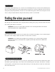
making your connections When connecting the security system’s wires to the vehicle wires it is important that the connections are tight and no bare wire is exposed. In this section, two types of connections are described that may be used to connect the wires from the security system to the vehicle’s wiring. Both types of connections are electrically acceptable if made correctly. Other types of "tap-in" connections, such as T-Taps are not acceptable. solderless butt connections 1.
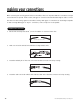
solder connections 1. Using your wire strippers and razor knife, strip approximately 1/2-inch of insulation off the wire to be connected to, without cutting the wire. Stripped Vehicle Wire 2. Twist the security module’s wire around the bare section of the vehicle’s wire. Vehicle Wire Module Wire 3. Solder the bare connection thoroughly using rosin core solder. Solder Soldering Iron Vehicle Wire Module Wire 4. Completely insulate the connection with electrical tape. © 2000 Directed Electronics, Inc.
primary harness (H1) wire connection guide This section of the installation guide describes in detail the connection of each of the primary harness wires. Also included are possible applications of each wire. This system was designed with the ultimate in flexibility and security in mind. Many of the wires have more than one possible function. Please read carefully to ensure a thorough understanding of this unit.
IMPORTANT! Never interrupt any wire other than the starter wire. NOTE: If connecting the H1/1 wire to control another module, such as a window controller (P/N 529T or 530T), a 1 amp diode (type 1N4004) will be required. Insert the diode as shown in the following diagram.
H1/3 WHITE/BLUE (+) TRUNK RELEASE, SENSOR SHUNT INPUT This input is used to bypass sensor inputs when the trunk is opened using the factory transmitter. Connect this wire to the (+) trunk release output of the factory keyless entry system or trunk release relay. When the system receives a (+) input on this wire, Zones 2 and 4 are bypassed for three seconds. If ground is applied to the H1/6 BLUE wire during that three-second period, Zones 2 and 4 will remain bypassed until the ground input is removed.
H1/6 BLUE (-) INSTANT TRIGGER, ZONE 1 This input will respond to a negative input with an instant trigger. It is ideal for hood and trunk pins or vehicles without factory Content Theft Deterrent (CTD). Vehicles without CTD may require trunk pins or need to be hard-wired to the alarm. (A trunk pin wire may need to be added if the vehicle does not already have a factory trunk pin.) The H1/6 BLUE wire will report on Zone 1.
H1/10 BROWN (+) SIREN OUTPUT Connect this wire to the red wire of the siren. Connect the black wire of the siren to (-) chassis ground, preferably at the same point that you connect the control module’s black ground wire. H1/11 RED (+) 12V CONSTANT POWER INPUT Before connecting this wire, remove the supplied fuse. Connect to the positive battery terminal or the constant 12V supply to the ignition switch. NOTE: Always use a fuse within 12 inches of the point you obtain (+)12V.
plug-in harnesses super-bright LED, 2-pin white plug The LED operates at 2V DC. Make sure the LED wires are not shorted to ground because the LED will be damaged. The LED fits into a 9/32-inch mounting hole. Be sure to check for clearance prior to drilling the mounting hole. valet/program switch, 2-pin blue plug The Valet/program switch should be accessible from the driver’s seat. It plugs into the 2-pin blue port of the control module.
operation mode settings standard vehicle security and operation features ARMING AND DISARMING WITH THE OEM TRANSMITTER When connected to the vehicle’s databus, the interface module can be armed and disarmed with the OEM keyless entry transmitter by pressing the lock and unlock buttons, respectively.
NOTE: Factory content theft deterrent (CTD) systems in Bonnevilles, Auroras and LeSabres do not monitor the trunk key cylinder wire; therefore, the trunk key cylinder sensor bypass feature is not available on these vehicles. The alarm will trigger if the factory trunk release feature on the OEM transmitter is not used when accessing the trunk while the databus interface module is armed. In Level I security mode, the H1/6 BLUE wire must be hard-wired to the vehicle’s trunk pin wire.
internal programming jumpers light flash jumper To access the jumper, open the control module. This jumper is used to determine the light flash output. In the default negative (-) position, the on-board relay is disabled and the unit will output (-) 200 mA, suitable for driving factory parking light relays. In the (+) position, the on-board relay is enabled and will supply a positive (+)12V on the H1/2 WHITE wire.
LEVEL II SECURITY MODE When this jumper is moved to the Level II position, the databus interface module will not disarm from the driver’s door or passenger door key cylinder. The trunk trigger zone will shunt if opened using the transmitter but will trigger when the key is used or if the trunk is forced open, regardless of whether the vehicle has OEM security content theft deterrent (CTD).
system features learn routine The System Features Learn Routine dictates how the unit operates. It is possible to access and change any of the feature settings using the Valet/program switch. To enter the System Features Learn Routine: 1. Open a door. 2. Key. Turn the ignition on, and then off. (The H1/9 YELLOW wire must be connected.) 3. Select a feature: Press and release the Valet/program switch the number of times corresponding to the feature you wish to program.
5. Release the Valet/program switch. ONCE THE FEATURE IS PROGRAMMED ■ Other features can be programmed. ■ The Learn Routine can be exited if programming is complete. TO ACCESS ANOTHER FEATURE After you have programmed a feature in Step 4 of the learn routine, press and release the Valet/program switch the number of times necessary to advance from the feature you just programmed to the next one you want to program. Then press the Valet/program switch once more and HOLD it.
4 DOOR TRIGGER INSTANT/DELAYED: In the instant (default) setting, if a door is opened while the security system is armed the system will trigger immediately. In the delayed setting there is a 15-second delay before the doors will trigger the system. This allows the user 15 seconds to disarm the system after a door is opened without the factory transmitter.
table of zones When using the diagnostic functions, use the Table of Zones to determine which input has triggered the system. It is also helpful in deciding which input to use when connecting optional sensors and switches. Zone Number Trigger Type Input Description One Instant Databus or H1/6 BLUE wire. Connect to optional hood/trunk pins. Two Multiplexed Heavy impact detected by the on-board Doubleguard shock sensor. Three Two-stage, progresses from warning to full alarm Door switch circuit.
■ Closing the door triggers the system, but opening the door does not: Have you correctly identified the type of door switch system? This often happens when the wrong door input has been used. (See the Finding the Wires You Need, Door Pin Switch Circuit section of this guide.
© 2000 Directed Electronics, Inc.