ROOM AIR CONDITIONER AP500PF SERVICE Manual AIR CONDITIONER CONTENTS 1. Precautions 2. Product Specifications 3. Operating Instructions and Installation 4. Disassembly and Reassembly 5. Troubleshooting 6. Exploded Views and Parts List 7. Block Diagrams 8. PCB Diagrams 9. Wiring Diagrams 10.
1. Precautions 1) Turn off the the power. Be sure to turn off the power before attempting to repair the unit such as the disassembly of the unit. Turn off the sub power switch separately installed. 2) Be careful of electric shock When checking the circuit with the power connected in unavoidable circumstances, take special care not to touch the live parts. There is a danger of electric shock.
2. Product Specifications 2-1 Table Model ITEM Size Unit Width x Height x Depth Packed Width x Height x Depth Unit Width x Height x Depth Outdoor unit Packed Width x Height x Depth Piping Packed Width x Height x Depth Weight Unit Indoor unit Packed Unit Outdoor unit Packed Piping Packed 1. Cooling capacity Electric characteristics 2. Power consumption(Cooling) 3. Current consuption(Cooling) 4. E.E.R 5. Noise Indoor unit Turbo (Cooling/ High Heating) Medium Low Outdoor unit Indoor unit 1.
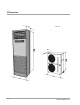
2-2 Dimensions Unit : mm 400 385 930 590 2-2 Samsung Electronics
3.
3-1-2 Key type and functions 3-1-2(a) PANEL key type and functions Key name On/off Mode selection Fan speed selection Temperature(time) setting(up) Temperature(time) setting(down) Change of display Key operating function Start and end of operation - ON 1 time = operation start, ON again = operation end.
3-1-2(b) LED display operating spec. Lamp name Operation lamp Operating spec. - When the power is applied, the lamp goes on and off in an interval of 0.5 seconds. - If the operation is changed to “on”, the lamp stops turning on and off and continues to remain on. - If the operation is changed to “off”, then LED off.
3-2 Installation 3-2-1 Selection of Installation Place 3-2-1(a) Indoor Unit • Install the unit at a place close to the wall facing the outside as it is necessary to perform piping connection with the outdoor unit. - It is effective to install the unit at a window side to ensure uniform distribution of indoor temperature. • Install the unit at a place where there is no obstacle against the wind around the air inlet and air outlet. • Install the unit horizontally at a stable, rigid place.
Installation Method 3-2-2 Electrical Work The electrical work should be performed by a specialist qualified for the work. • Use the three phase power supply, and be sure to install the sub power distributing board for exclusive use with the unit(separately purchased by the user). * Avoid octopus-type wiring as it can cause a drop in voltage, thus resulting in poor performance of the automatic control circuit. • Be sure to install circuit breaker (separately purchased by the user).
Installation Method 3-2-2(a) When connecting 3Phase 4wires 380V AC 1. Remove cover of electric box on side panel of outdoor unit. 2. Connect electric input wires (R,S,T,N) to each terminal (R,S,T,N) of the electric box on outdoor unit respectively. (Input wires are purchased by the user separately.) 3. Connect electric wires (red, white, black) to each terminal (red, white, black) on indoor and outdoor unit respectively.
Installation Method 3-2-2(b) When connecting 3Phase 3wires 220V AC 1. Remove cover of electric box on side panel of outdoor unit. 2. Connect electric input wires (R,S,T) to each terminal (R,S,T) of the electric box on outdoor unit respectively. (Input wires are purchased by the user separately.) 3. Connect electric wires (red, white, black) to each terminal (red, white, black) on indoor and outdoor unit respectively.
Installation Method 3-2-3 Installation Method 3-2-3(a) Installation Procedures 1. Open the inlet grille, and remove the flare nut. 2. Bend the connection pipe to an appropriate length using the spring bender depending upon the installation place. - Allowable pipe length : Maximum 25m - Allowable pipe drop distance : Maximum 15m - Make no more than ten bending points on the pipe • When the pipe length is in excess of the standard pipe length of 5m, add the refrigerant (R-22) of 50g for each additional 1m.
Installation Method 3-2-3(b) Connection of Refrigerant Piping Flare Processing 1. Cut the pipe using the pipe cutter. Oblique Roughness Burr 2. Insert the flare nut into the pipe, and then perform the flare processing. Outer Diameter ø 9.52mm ø 19.05 mm A ( out / in) 1.7 / 1.0 (mm) 2.2 / 1.5 (mm) • Unproper flaring Inclined Surface damaged Cracked Uneven thickness Pipe Bending 1. Perform bending of the pipe using the bender which has a specified bending radius. 2.
Installation Method 3-2-3(c) Drilling a Hole in the Wall • • Drill a hole of 70mm in diameter to the outside. The drilling should be done at a distance of less than 150mm from the floor facing the indoor unit. ø70mm Less than 150mm 3-2-3(d) Drain Hose • Extend the drain hose to the drain hose connected to the drain pan, and fix it with the tape or a cable tie to prevent separation. Then make a covering of it so that water can not flow outwardly.
4. Disassembly and Reassembly 4-1 Indoor Unit No Parts Procedure 1 Indoor unit 2 Inlet grille 1) Open the inlet grille and remove the connection ring. 3 Main PCB 1) Separate the PCB connect wire after separating the control box cover. Remarks 2) Separate the connection wire to separate the front cover and duct. 3) The main PCB should be separated by turn over the mountain tab.
Disassembly and reassembly No Parts Procedure 4 Font cabi 1) The front cabi should be separated by giving strength downward after loosening 2 screws at the lower end. 5 Plate top 1) The plate top should be separated by loosening screws.
Disassembly and reassembly No Parts 6 Ass’y grille out Procedure Remarks 1) First loosen screws at left and right sides of grille out. 2) Then the ass’y grille out should be separated by giving strength upward ( ↑). 7 Ass’y duct 1) First loosen the 4 screws at left and right sides. 2) Then the ass’y duct should be separated by lifting it.
Disassembly and reassembly No Parts 8 Evaporator Procedure Remarks 1) First separate the cover after loosening the screws fixed at evap cover R. 2) Ten separate the 3 screws fixed at cabinet BKT of evaporator BKT. 3) Evaporator should be separated by flinging ahead.
Disassembly and reassembly No Parts Procedure 9 Motor 1) When the ass’y duct should be separated from the motor, the 2 bracket should be separated first. Remarks 2) Then the bolts fixed at the blower and motor shaft should be separated. 3) Then the screws binding the holder top blower and duct should be separated. 4) The duct of one side should be separated as the picture shows after loosening the upper binder. 5) The binder of the motor and the duct should be separated.
Disassembly and reassembly No Parts Procedure Remarks 6) Then the motor should be separated. 7) The bracket fixed at the motor should be separated. 10 4-6 Panel PCB 1) Should be separated after loosening the insulating material and binders at the back of the front side.
Disassembly and reassembly 4-2 Outdoor Unit No Parts 1 Outdoor unit Procedure Remarks 1) Packaged air conditioner outdoor unit 2) The binders of the front side should be separated. 3) The flank and the binders should be separated from each other. 2 Control box Samsung Electronics 1) Connect distributed wires in the control box.
5. Troubleshooting Troubleshooting First, Items to be checked first Second, Check the corrective actions in the case of occurrence of self-diagnosis mode Third, When the trouble is not related to the 1st or 2nd items above, check the troubled area in detail in accordance with the fault analysis method by symptom.
5-3 Fault Analysis by Symptom 5-3-1 No Power (No display) 1) Checkpoints (1) Is the voltage of the power source normal?(AC 187V - AC 253V) (2) Is the power line in good contact? (3) Check the power fuse(F701, F702) and PCB fuse(F101) for open. (4) Are the primary and secondary sides of the power-trans in good contact with the connector? (5) Is the output voltage of REG1(KA7812) normal?(DC 11.5V - DC 12.5V) (6) Is the output voltage of REG2(KA 7805) normal?(DC 4.5V - DC 5.
Troubleshooting 5-3-2 When the Indoor Fan Motor does not Operate. 1) Checkpoints (1) Is the voltage of the power source normal?(AC 187V-AC 253V) (2) Is the indoor fan connector (CN71) in good contact? (3) Is the starting condensor of the fan motor in good contact with the terminal? (4) Is the resistance at both ends of the relay coil approximately 400L? 2) Checking procedures(after checking the checkpoints of clause 1) Turn off the power, and then turn it on in 5 seconds.
Troubleshooting 5-3-3 When the Compressor Does not Operate 1) Checkpoints (1) Is the voltage of the power source normal?(AC 187V - AC 253V) (2) Is the desired temperature set at a higher level than the current temperature at the time of “Cool” operation? (3) Is the power-in good contact with the comp. connector(GT 1, 2, 3)? (4) Check the wirings of the outdoor and indoor unit for a wrong connection or poor contact.
Troubleshooting 5-3-4 When the Remote Controler Does not Operate 1) Checkpoint The sounds “beep” when it receives the signal of the remote control. 2) Checking procedures Turn off the lower, and then turn it on in 5 seconds. Is room temperature displayed on the temperature indicator and does the operation start when pressing the on/off button on the panel? N Refer to the checkpoint when the power is not supplied.
5-4 PCB Inspection 5-4-1 Inspection Precautions 1) Be sure to check whether the AC sub power switch is removed when removing the main PCB or panel PCB. 2) Do not hold the outside of the main PCB or panel PCB with the hand or aply excessive force to it. 3) When connecting or removing the connector to the main PCB or panel PCB, do not pull the lead wire, but hold the entire assembly with the hand. 5-4-2.
6.
Exploded Views and Parts List ■ PART LIST Q’TY No 1 2 3 4 ● ● 5 6 7 8 9 10 11 12 13 14 15 ● 16 17 18 19 20 ● 21 22 23 24 25 26 27 28 29 30 31 32 ● ● 33 34 35 36 37 38 39 40 41 42 43 44 45 46 47 48 CODE-NO DB70-10271A DB90-10561A DB90-20171B DB91-90012B DB90-40113A DB90-40113L DB90-10175A DB64-50076A DB63-10027A DB63-10432A DB93-40232L DB93-40232S DB64-30011D DB64-50019A DB64-50020A DB64-50069A DB61-30501A DB74-10079A DB92-10007B DB67-90005A DB61-30108A DB61-30109A DB64-10035A DB64-10036A DB92-10298A D
6-2 Outdoor Unit 6-2-1 Outdoor Unit 6-3 Samsung Electronics
Exploded Views and Parts List ■ PART LIST Q’TY No DESCRIPTION CODE-NO SPECIFICATION REMARKS AP500PF 1 DB90-10565A ASS’Y-CABI OUT AIR WELD GUARD FAN 1 2 DB63-30028C GUARD-INLET SC-91438T, - 1 3 DB67-50067A FAN-PROPELLER AS+GF20, D495, 4BLADE 2 4 DB95-20137A ASS’Y-MOTOR OUT AP-1100, OSM-6508SRC 1 5 DB95-20137B ASS’Y-MOTOR OUT AP-1100, OSM-6508SRC WIRE 1 6 DB90-30028E ASS’Y-MOUNT MOTOR OUT APE-1600CR, - 1 7 DB61-40088A HOLDER-FRAME SGCC1, T1.
Exploded Views and Parts List 6-2-2 ■ Parts List No CODE NO Description Specification Q’ty 1 DB93-40419A ASS'Y CONTROL BOX OUT SGCC-M, Z(Z=22) 1 2 P6523-0030-00 CAPACITOR START 330VAC 130~156MFD 1 3 2501-001098 CAPACITOR OUT 450VAC 40/4uF 1 4 2501-001098 CAPACITOR OUT 450VAC 4uF 1 5 DB34-90057B MAGNET-CONTACTOR 25A 1 6 DB69-20117B TERMINAL BOARD 600V 35, 15A 1 7 DB34-90053C MAGNET-CONTACTOR MUF20Ba1b 1 8 DB26-30001A TRANS INDUCTOR 220VAC 20A 8.
Exploded Views and Parts List 6-3 Remote Control 2 5 1 3 6 4 ■ Parts List No CODE NO Description Specification Q’ty DB93-30026J ASS’Y-REMOCON AR-C60 1 1 DB61-10022A CASE-REMOCON(UPP) ABS 1 2 DB61-10011A CASE-REMOCON(LW) ABS 1 3 DB73-20013A RUBBER(BT) NBR 1 4 DB93-10463A ASS’Y-REMOCON PCB AP-500PF 1 5 DB64-40008J WINDOW-REMOCON PC T1.
7.
Troubleshooting 7-2 Refrigerating Cycle Block Diagram INDOOR UNIT Capillary Heat exchanger (Evaporator) Heat exchanger (Condenser) Compressor High Pressure S/W OUTDOOR UNIT * Additional supplementary amount per meter for extension: When you utilize more than 5m of the tube, you must supplement 50g of R-22 freezing catalyzer gas per additional meter. Refrigerating cycle temperature and pressure STD Pressure Operating Condition Indoor T1 T2 Outdoor DB WB DB WB Standard 4.5~5.
8.
PCB Diagrams ■ PARTS LIST DESIGN LOCATION SK1 F701, F702 F101 VAR1 RY1-RY6 C701 C702 CN11 CN41 CN42 CN91 CN92 CN93 CN71 IC1 IC2 IC3, IC5 IC4 Q601, Q602 Q401 REG1 REG2 D101-D105 D907 X1 BZ61 C102 C103 C104 C501 C104-C110, C201, C202 C401-C408 C901, C902 C903 R201, R201 R401, R403, R411-R414 R501, R502, R601, R901 R902 R402 R405, R406 R404 R407, 408, R410, R912 R602 R903-R911 Samsung Electronics CODE NO Description DE62-30031A DE47-30019A 3601-001094 DB47-90053A DB47-90014A 3501-001042 2306-000111 2301-0
8-2 Ass’y Panel PCB(Code No : DB93-10469A) 8-3 Samsung Electronics
PCB Diagrams ■ PART LIST DESIGN LOCATION CODE NO Description Specifition Q’TY R1 2001-000065 R-CARBON RD 1/4 T 103-J 1 C1 2401-003107 C-ELECT CE 04 C 16V 470-M 1 C2 2201-000144 C-CERAMIC CK OA 50V T 104-Z 1 - DB32-50023A MODULE REMOCON TSOP-1238 TB1 1 D1-04 DB47-90011A DIODE SW 1N4148 1.2V 4 LE1 DB07-10050A LED LAMP LTL-4212 RED T P10.
9. Wiring Diagrams 9-1 Indoor Unit MARK NAME SK1 SPARK KILLER VAR1 VARISTOR FM FAN MOTOR RTH ROOM THERMISTOR SM L.R SWING MOTOR RY1 COMPRESSOR DRIVE RELAY RY2 L.
9-2 Outdoor Unit • 3 phase 4 wire 380V 9-2 WIRE COLOR MARK NAME 52C COMP MAGNET SWITCH B BLK FM1,2 FAN MOTOR W WHT C1,2 FAN MOTOR CAPACITOR R RED 63H HIGH PRESSURE SWITCH G GRN CH CRANK CASE HEATER BL BLU S1,S2 COMP O.L.
Wiring Diagrams • 3 phase 3 wire 220V Samsung Electronics WIRE COLOR MARK NAME 52C COMP MAGNET SWITCH B BLK FM1,2 FAN MOTOR W WHT C1,2 FAN MOTOR CAPACITOR R RED 63H HIGH PRESSURE SWITCH G GRN CH CRANK CASE HEATER BL BLU S1,S2 COMP O.L.
10.
10-2 Remote Control Samsung Electronics 10-2
UPDA TE LOG SHEET Application date Page Part# Note(Cause & Solution) S/Bulletin# Use this page to keep any special servicing information. (Service Bulletin, etc.) If only parts number changes, Just change parts number directly on parts list. And if you need more information, please see the service bulletin Copyright Trademarks ®œ 1995 by Samsung Electronics Co., Ltd. All rights reserved.