AM1 Security System installation guide © 2003 Directed Electronics, Inc.
NOTE: This product is intended for installation by a professional installer only! Any attempt to install this product by any person other than a trained professional may result in severe damage to a vehicle’s electrical system and components.
contents installation guide . . . . . . . . . . . . . . .1 what is included . . . . . . . . . . . . . . . .3 integrated LED/Valet® switch . . .21 data port—Bitwriter® . . . . . . . .21 installation points to remember . . .3 before beginning the installation: 4 after the install: . . . . . . . . . . . . . .4 four-pin optional sensor harness .22 RED wire . . . . . . . . . . . . . . . . . .22 BLACK wire . . . . . . . . . . . . . . . .22 BLUE, GREEN wires . . . . . . . . . .22 tools required . . . . . . . .
ii © 2003 directed electronics, inc.
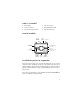
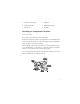
what is included z Control module z 4-pin sensor harness z 12-pin main harness z Integrated LED/Valet switch z 7-pin door monitor/Aux harness z 3-pin door lock harness control module OPTIONAL RECEIVER (NOT USED) DEALER MASTER CONTROL LOOP BITWRITER® SHOCK SENSOR ADJUSTMENT 7-PIN DOOR MONITOR/ AUX HARNESS DOOR LOCK 10-AMP FUSE/JUMPER ACCESS LED (INTEGRATED LED/ VALET® SWITCH) VALET® (INTEGRATED LED/VALET SWITCH) 12-PIN MAIN HARNESS OPTIONAL SENSOR INPUT (506T OR 504D) installation point
Do not disconnect the battery if the vehicle has an anti-theft coded radio. If equipped with an airbag, avoid disconnecting the battery if possible. IMPORTANT! Please read this entire installation guide before beginning the installation. The installation of this security system requires interfacing with many of the vehicle’s systems. Many new vehicles use low-voltage or multiplexed systems which can be damaged by low resistance testing devices, such as test lights or logic probes.
z Solderless terminal crimpers z Drill bit set z Cordless power drill z Phillips head screwdriver z Torx driver set z Work light deciding on component location control module Never put the control module in the engine compartment! The first step in hot-wiring a vehicle is removing the driver's side underdash panel to access the starter and ignition wires. If the control module is placed just behind the driver's side dash it can easily be disconnected.
integrated LED/Valet® switch Things to remember when positioning the integrated LED/Valet® switch: • It should be visible from both sides and the rear of the vehicle, if possible. • It needs at least 1-1/2" clearance to the rear. • It is easiest to use a small removable panel, such as a switch blank or a dash bezel. Remove it before drilling your 5/16" hole.
IMPORTANT! Do not remove the fuse holder on the red (H1/11) wire. It ensures that the control module has it’s own fuse, of the proper value, regardless of how many accessories are added to the main power feed. finding the 12V switched ignition wire The ignition wire is powered when the key is in the run or start position. This is because the ignition wire powers the ignition system (spark plugs, coil) as well as the fuel delivery system (fuel pump, fuel injection computer).
finding a parking light wire The parking light wire is often found near the switch. Many cars have the switch built into the turn signal lever, and in these cars the parking light wire can be found in the steering column. The same wire is often available in the kick panel or running board. (+) parking light wire Use the following procedure to find (+) parking light wire with your multimeter. 1. Set to DCV or DC voltage (12V or 20V is fine). 2. Attach the (-) probe of the meter to chassis ground. 3.
4. Turn on the parking lights. If your meter shows (+)12V, turn off the parking lights and make sure it goes back to zero. 5. If it does return to zero, turn the parking lights back on and, using the dash light dimmer control, turn the brightness of the dash lights up and down. If the meter changes more than a volt when using the dimmer, look for another wire. If it stays relatively close to (+)12V, you have found your parking light wire.
main harness wire connection guide main harness wiring diagram H1/1 ___ ORANGE H1/2 ___ WHITE H1/3 ___ WHITE/BLUE H1/4 ___ BLACK/WHITE H1/5 ___ GREEN H1/6 ___ BLUE H1/7 ___ VIOLET H1/8 ___ BLACK H1/9 ___ YELLOW (+) Ignition Input H1/10 ___ BROWN (+) Siren Output H1/11 ___ RED H1/12 ___ RED/WHITE (-) 200mA Auxiliary Channel/Delayed Accessory Output (-) 500mA Ground When Armed (+)/(-) Light Flash Output No Function (-) 200mA Domelight Supervision Output (-) Door Trigger Input (-) Ins
IMPORTANT! Never interrupt any wire other than the starter wire. H1/2 WHITE light flash output: As shipped, this wire should be connected to the (+) parking light wire. It will supply a (+) 10A output. If the light flash polarity fuse jumper inside the unit is moved to the opposite position (see Internal Jumpers), this wire supplies a (-) 10A output. This is suitable for driving (-)parking light wires. © 2003 directed electronics, inc.
LIGHT BULB (+) 12V WHITE H1/2 (-) LIGHT FLASH OUTPUT PARKING LIGHT RELAY OR SWITCH H1/3 WHITE/BLUE no function. H1/4 BLACK/WHITE (-) 200 mA domelight-supervision output: Connect this wire to the optional domelight supervision relay. IMPORTANT! This output is only intended to drive a relay. It cannot be connected directly to the domelight circuit, as the output cannot support the current draw of one or more bulbs. H1/5 GREEN (-) door trigger input: Most vehicles use negative door trigger circuits.
H1/6 BLUE (-) instant trigger: This input will respond to a negative input with an instant trigger. It is ideal for hood and trunk pins and will report on zone one. H1/7 VIOLET (+) door trigger input: This wire is used in vehicles that have a positive (+) switched dome light circuit . Connect the violet wire to a wire that shows (+)12V when any door is opened, and ground when the door is closed.
H1/9 YELLOW (+) ignition input: Connect this wire to the (+)12V ignition wire. This wire must show (+)12V with the key in Run position and during cranking. Take care to insure that this wire cannot be shorted to the vehicle chassis at any point. H1/10 BROWN (+) siren output: This output can be used if an optional siren is installed. Connect this to the RED wire of the siren. Connect the BLACK wire of the siren to (-) chassis gound, preferably at the same point as the control module’s BLACK ground wire.
used to control optional accessories. If programmed for delayed accessory output, this wire will provide (-) ground when the ignition is turned off and will continue to output (-) ground until a door is opened then closed. This can be used to energize the accessory circuit in the vehicle to keep the radio and other accessories on after the ignition is turned off.
auxiliary harness wiring guide H2/1 BROWN (-) horn honk output: This wire supplies a 200 mA (-) output that can be used to honk the vehicle’s horn. It provides a pulsed output when the security system is armed/disarmed and in the triggered sequence or in panic mode. In most vehicle’s with (-) horn circuits this wire can control the vehicle’s horn without adding a relay. If the vehicle has a (+) horn circuit, an optional relay must be used to interface with the vehicle’s horn circuit.
In this case, find the driver’s door unlock motor wire. In most vehicle’s this wire can be found in the driver’s kick panel. H2/5 GRAY trunk release/sensor shunt input: This input is used to bypass the sensor inputs when the trunk is opened using the factory keyless entry system or trunk release relay. When the system receives a (+) input on this wire, zones 2 and 4 (if set in the features settings) are bypassed for 3-seconds.
keyless entry systems—three types There are three main types of keyless entry systems. Systems that unlock the driver’s door first and have internal relays, systems that unlock the driver’s door first but have external relays, and systems without driver’s priority door unlock. factory remote—driver’s door unlock 18 © 2003 directed electronics, inc.
external relays—driver’s door unlock This system is used in many four-door GM sedans. To test for this type of system, probe the unlock wire from the interior switch (black or white). Unlock the driver’s door, by itself, using the factory remote. If the switch wire shows (+) 12V, then use the following diagram: NOTE: It is often easy to access the passenger unlock wire going to the rear door motor on the driver’s side. © 2003 directed electronics, inc.
no priority—driver’s door unlock This type of keyless entry system is common in import vehicles as well as many Jeep vehicles. When unlocking the doors with the transmitter all doors unlock at the same time. The following diagram shows how to install the system and prevent disarming from the interior lock switch. NOTE: Failure to insert the diodes at the correct point will allow the system to be disarmed by one of the power door lock switches inside the vehicle.
door lock harness wire connection guide H3/A ___ GREEN H3/B ___ H3/C ___ BLUE (-) Lock, (+) Unlock Output Not Used (-) Unlock, (+) Lock Output The control module can control 2 common power door lock types without any additional parts. With certain verhicles, or if an actuator is to be installed, either a 451M Door Lock Relay Satellite or two relays will be required. Refer to TechTips document 1041.
four-pin optional sensor harness RED wire The red wire supplies constant power to the optional sensor. BLACK wire The black wire supplies ground to the optional sensor. BLUE, GREEN wires The blue and green wires are multiplex inputs. They are both tied to the same zone. If an input of less than 0.8 seconds is supplied to either wire the Warn-Away® response will occur. An input longer than 0.8 seconds to either wire will initiate the triggered sequence and report zone 4.
to learn lock: 1. Open a door. 2. Within 5-seconds: Press and release the integrated LED/Valet® switch once. 3. Within 5-seconds: Turn the ignition On and then Off (leave for less than 2-seconds in the on position). 4. Within 5-seconds: Press and hold the integrated LED/Valet® switch. The LED will flash to indicate that the lock routine is ready to be learned. 5. Press lock button: Press the lock button on the factory transmitter.
to exit the learn routine: Do one of the following: 1. Close the open door. 2. Turn the ignition on. 3. No activity for longer than 15 seconds. 4. Press the integrated LED/Valet® switch too many times. on-board dual stage shock sensor Less Sensitive More Sensitive There is a dual-stage shock sensor inside the control module. Adjustments are made via the rotary control as indicated above.
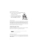
internal programming jumper A 10A fuse is used as both a fuse and a program jumper. This jumper determines the light flash output polarity. In the (+) position, the on-board relay is enabled and the unit will output (+)12V on the WHITE wire, H1/2. In the (-) position, the on-board relay is enabled for (-) output on the WHITE wire, H1/2. To access the jumper, remove the sliding door from on top of the control module, as shown below. FUSE/JUMPER (-) POSITION © 2003 directed electronics, inc.
zones Zone Trigger Type Number Input Description 1 Instant trigger Hood and/or trunk pin switches. 2 Multiplexed input Heavy impact from on-board Doublegurard® shock sensor. 3 Two-stage, progresses from warning Door switch circuit. to full alarm 4 Multiplexed Optional sensor, Inputs shorter than 0.8 seconds will trigger Warn Away® response, while inputs longer than 0.8 seconds will instantly trigger full alarm. 5 Two-stage (similar to zone 3) Ignition input.
two times followed by a pause and then flash three times followed by a pause. NOTE: The Warn Away® response does not report on the LED. The Long Term Event History will exit if the ignition is turned off or there is no activity for 60-seconds. rapid resume logic The current state of the alarm will be stored in non-volatile memory. If power is lost and then reconnected, the system will recall the stored state from memory (arm, disarm, and Valet® mode).
to enter feature programming routine 1. Open a door. 2. Turn the ignition on and then off. 3. Within 5-seconds, press and hold the integrated LED/Valet® switch. After 3-seconds the horn will sound once to indicate entry into the first features menu. To select the second features menu, continue to hold the integrated LED/Valet® switch until the horn sounds twice. Once the desired menu is selected, release the integrated LED/Valet® switch. 4.
z After 3-seconds, the unit will advance to the next menu and the horn will sound the number of times corresponding to the menu selected (once or twice). exiting feature programming z Close the door. z Turn the ignition On. z No activity for 15-seconds. z Press and release the integrated LED/Valet® switch too many times. features #1 menu Default settings are shown in bold.
Feature steps 5 and 6 are related. If Auxiliary Output Enabled is selected in feature 5 then either Auxiliary Output or Delayed Accessory Output can be selected in feature step 6. Examples of this are where Auxiliary Output is used to provide a momentary 800msec pulse on the RED/WHITE wire of the main harness (can be used for opening the trunk). The delayed accessory output is used to allow selected vehicle accessories to remain on (such as radio) when the ignition is turned off.
master dealer remotes A master dealer remote can be programmed into the system for demonstration purposes. Generally, each salesman would carry a remote that would operate all the cars on the lot equipped with this system. The dealer remotes are binary transmitters that are detuned slightly in order to limit transmitting range. The dealer remote can be taught to the system by following the Transmitter Learn Routine. NOTE: This system is shipped without a receiver.
troubleshooting starter kill does not work: z Is the correct starter wire being interrupted? If the car starts when the starter kill relay is completely disconnected, the wrong starter wire has been cut and interrupted. • Is the yellow wire connected to “true” ignition? Make sure this wire is connected to a wire that has power in the run and start positions. the Valet® switch does not work. • Is it plugged into the correct socket? See the integrated LED/Valet® Switch section.
wiring quick reference guide © 2003 directed electronics, inc.
34 © 2003 directed electronics, inc.