FEMTOSECOND MULTIPASS TI:SAPPHIRE AMPLIFIER Wedge 50 User’s Manual
TABLE OF CONTENTS 1. Introduction 2. Principles of operation 3. Laser safety 4.
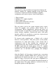
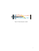
1. INTRODUCTION This manual describes installation and operation of Wedge 50 titanium : sapphire (Ti : sapphire) amplifier system. The system is based on a femtosecond confocal multipass amplifier configuration and consists of parts, shown in the Figure 1: 1. Pulse stretcher 2. Multipass Ti : sapphire amplifier 3. Pulse compressor 4. Pulse picker and Pockels cell driver 5.
After amplification, the picosecond pulses are temporally compressed to 50 - 100 fs pulses (depending on the input pulse duration) by one-grating pulse compressor. At the pumping with a frequency doubled Nd: YLF pumping laser (1000 Hz, 20 mJ/ pulse), the compressor gives 1.0 mJ pulses at 800 ± 20 nm. Wedge 50 femtosecond amplifier system comprises: 1) Optical unit of two-mirror confocal multipass amplifier with installed inside stretcher, pulse picker with HV Pockels cell driver, and pulse compressor.
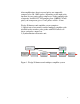
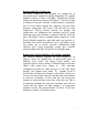
2. PRINCIPLES OF OPERATION Femtosecond Pulse Stretcher Temporal pulse stretching is required in avoiding the effects of peak power damage in high energy ultrafast amplifiers. This peak power damage is due to the tendency of bright beams to self focusing (a result of non-linearity in the index of refraction), which makes it necessary to limit the intensity present in amplifiers. The technique of chirped pulse amplification (CPA) gives a possibility to avoid this obstacle.
IN OUT VR1 SM G1 PM Figure 2.
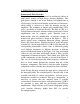
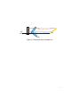
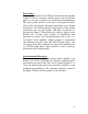
Femtosecond Pulse Compressor The pulse compressor was designed for compression of picosecond pulses amplified by Wedge 50 multipass Ti: sapphire amplifier to pulses as short as 50-100 fs. The principle of pulse compressor operation is shown in the Figure 3. One can see that in contrast to the pulse stretcher, redder frequency components have to travel further through the compressor than the bluer frequency components. The result is that the pulse has been compressed.
IN OUT G2 VR2 HR1 Figure 3.
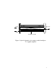
pump optic axis output input M1 Ti:sapphire crystall M2 Figure 4.
Pulse Picker A pulse picker installed in the Wedge 50 femtosecond amplifier system is used for one pulse selection from a train of stretched pulses. As a result, seed pulses are formed for the amplification. The pulse picker utilizes well known electrooptical Pockels effect. Pulse train having horizontal polarization goes through the Pockels cell. Without applied voltage pulses do not change polarization and exit pulse picker with help of polarizers as shown in the Figure 5.
Nd:YLF Power Supply Synch. out Q-switch Synchronization electronics unit 50 Hz HV Driver Photodiode (to trigger) Pockels Cell Optic Beam Pulse picker from Ti:Sapphire oscillator Figure 5. Pulse picker and synchronization electronics.
4. LASER SAFETY Please read next page carefully before you start an installation WARNING ! LASER SAFETY Be very careful executing any step of alignment. Avoid any exposure to the directed and reflected laser beams. Direct and reflected laser radiation from pump lasers and Ti: sapphire amplifier can cause serious eye damage. Remember, that Ti: sapphire radiation is invisible or looks like as red radiation of small intensity. However, it is dangerous even at lowest intensity.
DANGER VISIBLE AND /OR INVISIBLE LASER RADIATION AVOID EYE OR SKIN EXPOSURE TO DIRECT OR SCATTERED RADIATION CLASS IV LASER PRODUCT 13
4. OPTICAL ALIGNMENT Figure 6 shows optical layout of the Wedge 50 amplifier system. Below you will find legends for all optical elements shown in the figure.
Y2 M9 L1 M8 IN BS1 AM2 SM M1 IN OUT M5 A1 VR1 A4 P2 PC TIS G1 R P1 F G2 P0 Y3 A2 PM A5 VR2 M2 AM1 IN M7 M6 to pin-diode OUT BS2 A3 HR1 Figure 6.
STRETCHER GRATING ALIGNMENT. 1. Replace the rotation stage with the grating G1. Set position of rotation stage to “0”. 2. With rotation stage set so that the zero order beam from the stretcher grating goes back through aperture A1, adjust the vertical and horizontal tilts of the grating mount for best alignment to aperture A1. 3. Set rotation stage at 14 degrees for 800 nm. Littrow (auto collimated) diffracted beam should go back through A1. 4.
third reflected from the SM beam hits the PM. The reflected from the PM beam hits the SM at the height of 108 cm. The fourth reflected from the SM beam hits the G1 at the height of 108 cm, too. The fourth reflected from the G1 beam hits the mirror M1. Radiation pattern on the stretcher grating G1 is shown in the Figure 7: Figure 7. CW radiation pattern on the stretcher grating If the spot No 3 is not aligned vertically with one another, a small horizontal rotation of the VR1 should be done.
(PO has been installed at 45o position). Get maximum of the average power. Press the clamp of R. 2. Direct the through F with help of M2. PULSE PICKER ALIGNMENT 1. Remove Pockels cell PC and polarizers P1 and P2. 2. Adjusting M1, direct beam reflected by M1 to the center of M2. 3. Adjusting M2, direct beam reflected by M2 to the center of M3 and M4. Mirrors M3 and M4 serve for 90o polarization rotation. 4. Replace P1 and adjust it. The input beam should hit the center of P1.
2. With help of M4 and M5 direct the beam into apertures A4, A5. Remove A4, A5. In case of aligned amplifier go to step 16. Go to step 4 if it is necessary to make amplifier alignment. 3. With help of M3 and M4 direct beam onto left side of M5. 4. With help of M4 and M5 direct beam parallel to the breadboard at the level 132 mm above the breadboard. 5. Place amplifier mirror AM1 (R=1000 mm) and AM2 (R=830 mm) at the distance 915 mm between metal clamps. The distance between AM2 and M5 should be 10 cm. 6.
11. Moving narrow paper strip through beams between AM1 and AM2 find common for AM1 and AM2 focal point. 12. With horizontal control of AM2 tune the beams configuration to get 40-41 cm distance between AM2 and common focal point. 13. Place the titanium : sapphire crystal assembly to the common for AM1 and AM2 focal point. A movement of the lowest translation stage should be parallel to the M5-AM1 beam. 14. Aligned multipass configuration will be broken after the step.
5. If not, adjust rotation of the grating about it‟s face for best vertical alignment to the A3 by carefully loosening the retaining screw in the grating mount so that the grating holder can be rotated in the mount. Caution: grating holder can fall from tilt stage if this step is not performed carefully or if retaining screw is too loose.. 6. Reiterate between step 3 (adjust only the vertical tilt of the mount) and step 4 (adjust only the rotation of the grating) until no further adjustment is necessary.
height of this stripe requires adjustment, move VR2 in vertical direction by loosening two bolts. 5. The beam should now reflect off the HR1 a final time before reflecting off the upper right corner of the grating in the form of a spot. The beam should now be exiting the amplifier optical unit above the mirror M7 and through the output port. The height of the final compressed beam is adjusted with HR1 assembly. 6.
6. Watch amplification with pin-diode and oscilloscope, slightly moving pump beam with external mirror. 7. Get maximum amplification slightly adjusting AM1, L1, Y3, and M5. 8. Pulse amplification is determined by amplification saturation level. An amplification saturation is highest when only 3-4 amplified pulses are detected with oscilloscope. 9. Check energy of amplified pulses at 8-pass amplifier configuration, Epump = 20 mJ, and 750 pump beam diameter inside the TIS.