
User`s manual

14
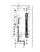
4. OPTICAL ALIGNMENT
Figure 6 shows optical layout of the Wedge 50 amplifier system.
Below you will find legends for all optical elements shown in the
figure. These conventional signs will be used through the
Chapter:
TIS – Ti : sapphire crystal
AM1 - spherical amplifier mirror
AM2 - spherical amplifier mirror
G1 - G2 - stretcher and compressor gratings, respectively
L1 - lens
SM - stretcher spherical mirror
PM - stretcher plane mirror
VR1- stretcher vertical retroreflector
VR2- compressor vertical retroreflector
HR1- compressor horizontal retroreflector
P1, P2, P0 - polarizers
PC - Pockels cell
M1 – M9 - mirrors, high reflectors at 800 nm
Y1 – Y3 – mirrors, high reflectors at 532 nm
A1 – A5 - apertures
BS1 – BS2 – beamsplitters
R – half wave plate
F – Faraday rotator
INPUT BEAM ALIGNMENT
1. Remove the rotation stages with gratings from the breadboard.
2. Operate the Ti : sapphire seed oscillator in continuous wave
regime at 800 nm.
3. Input beam should be aligned through apertures A1, A2 and
A3 at a beam height of 120 mm above the breadboard.