PUMP
SEED
M8
M9
L1
Y2
Y1
BS1
to trigger
SM
VR1
M2
M3,M4
P2
P1
PC
F
P0
G1
G2
M1
HR1
VR2
M7
BS2
M6
AM1
M5
AM2
TIS
Y3
to pin-diode
PM
A5
A4
A1
A2 A3
OUT
IN
OUT
IN
OUT
IN
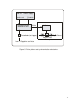
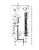
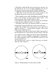
Figure 6. Schematic layout of multipass amplifier, pulse stretcher, pulse picker, and pulse compressor
R