
User`s manual

17
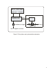
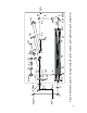
third reflected from the SM beam hits the PM. The reflected
from the PM beam hits the SM at the height of 108 cm. The
fourth reflected from the SM beam hits the G1 at the height of
108 cm, too. The fourth reflected from the G1 beam hits the
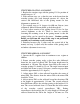
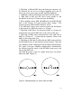
mirror M1. Radiation pattern on the stretcher grating G1 is
shown in the Figure 7:
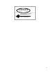
Figure 7. CW radiation pattern on the stretcher grating
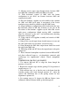
If the spot No 3 is not aligned vertically with one another, a
small horizontal rotation of the VR1 should be done. When the
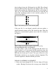
Ti:Sa laser is mode-locked, pattern seen on the G1 is shown in
the Figure 8:
Figure 8. Femtosecond radiation pattern on the stretcher grating
PLANE MIRROR (PM) ALIGNMENT
You must check a view of the reflected from M1 beam on a
distance about 3 m. If you moved the PM translation stage, the
shape of the beam is changed. You must find the position of the
PM when the beam spot is round. Two spots observed on the
PM should coincide in case of perfect stretcher alignment. The
stretcher alignment is finished with this procedure.
FARADAY ASSEMBLY ALIGNMENT
1. Direct the beam through R, PO. Do the clamp of R more
weaker. Rotating R measure the average power behind PO