
User`s manual

18
(PO has been installed at 45
o
position). Get maximum of the
average power. Press the clamp of R.
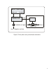
2. Direct the through F with help of M2.
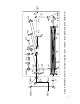
PULSE PICKER ALIGNMENT
1. Remove Pockels cell PC and polarizers P1 and P2.
2. Adjusting M1, direct beam reflected by M1 to the center of
M2.
3. Adjusting M2, direct beam reflected by M2 to the center of
M3 and M4. Mirrors M3 and M4 serve for 90
o
polarization
rotation.
4. Replace P1 and adjust it. The input beam should hit the center
of P1. P1 should be oriented for transmission of light having
horizontal polarization.
5. Replace P2 and adjust it. The input beam should hit the center
of P2.
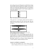
6. Place white screen (white paper sheet) after P2 and observe
transmitted by P2 light with IR viewer. Mark spot position by a
pencil.
7. Rotating P2 find minimum transmutation.
8. Replace PC and adjust it. The input beam should hit the center
of PC.
9. Place a sheet of scattering paper (for example, a sheet of
optical cleaning paper) between P1 and PC.
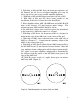
10. With help of IR viewer observe on the screen a spot of the
transmitted light. The spot looks like dark cross. Adjusting PC,
coincide the center of the cross with the mark on the screen.
11. Remove the scattering paper.
12. Achieve minimum light transmutation through P2 by fine
adjustment of PC.
AMPLIFIER ALIGNMENT
1. Place a half wave plate between P1 and PC or between PC
and P2.