
User`s manual

19
2. With help of M4 and M5 direct the beam into apertures A4,
A5. Remove A4, A5. In case of aligned amplifier go to step 16.
Go to step 4 if it is necessary to make amplifier alignment.
3. With help of M3 and M4 direct beam onto left side of M5.
4. With help of M4 and M5 direct beam parallel to the
breadboard at the level 132 mm above the breadboard.
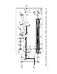
5. Place amplifier mirror AM1 (R=1000 mm) and AM2 (R=830
mm) at the distance 915 mm between metal clamps. The
distance between AM2 and M5 should be 10 cm.
6. Set AM1 hole centers at the same level above the breadboard
as the beam level. AM2 hole center is at 142 mm.
7. With help of M5 direct the beam onto AM1 to a distance 18
mm from the edge of the AM1 hole to the center of the spot.
8. With help of AM1 direct reflected beam to the right side of
AM2 to a distance 17 - 18 mm from the symmetry center of the
AM2 to the center of the spot.
9. With help of AM2 direct reflected from AM2 beam parallel to
the M5-AM1 beam (47 mm distance between beams). After this
step, multipass beam configuration will be aligned automatically.
Six-, eight-, or ten-pass amplifier configuration is determined by
the distance from the center of the M5-AM1 beam spot to the
edge of the AM1 hole.
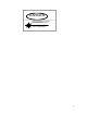
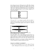
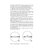
10. With IR viewer watch six (eight) beam spots on mirrors
AM1 and AM2 (Figure 9).
Figure 9. Radiation pattern on mirrors AM1 and AM2