
User`s manual
20
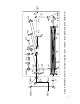
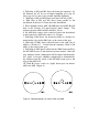
11. Moving narrow paper strip through beams between AM1
and AM2 find common for AM1 and AM2 focal point.
12. With horizontal control of AM2 tune the beams
configuration to get 40-41 cm distance between AM2 and
common focal point.
13. Place the titanium : sapphire crystal assembly to the common
for AM1 and AM2 focal point. A movement of the lowest
translation stage should be parallel to the M5-AM1 beam.
14. Aligned multipass configuration will be broken after the step.
By horizontal control of M5 take all beams to one spot on the
left surface of the titanium : sapphire crystal. After that, restore
eight passes configuration slightly moving AM1 translation
stage in a direction “to the user”, and simultaneously adjusting
horizontal control of AM1.
15. Using controls of Ti:sapphire assembly and controls of AM1
and AM2 get that:
a) Going to the crystal input beams should intersect in one and
the same point on the crystal surface (use microscope).
b) Going through the AM1 hole output beam should not touch
the edge of the AM1 hole.
16. With help of M6 and M7 direct the output beam to the pulse
compressor.
17. Place substrate beamsplitter anywhere between M6 and M7
and direct reflected beam to pin-photodiode connected with
oscilloscope for amplification control. Watch unamplified
pulses.
COMPRESSOR GRATING ALIGNMENT.
1. Use mirrors M6 and M7 to align the beam though the
apertures A3 and A2.
2. Replace the rotation stage with the grating G2. Set position of
rotation stage to “0”.
3. With rotation stage set so that the zero order beam from the
stretcher grating goes back through aperture A3, adjust the
vertical and horizontal tilts of the grating mount for best
alignment to aperture A3.
4. Set rotation stage at 14 degrees for 800 nm. Littrow (auto
collimated) diffracted beam should go back through A3.