
User`s manual

22
height of this stripe requires adjustment, move VR2 in vertical
direction by loosening two bolts.
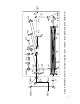
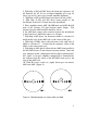
5. The beam should now reflect off the HR1 a final time before
reflecting off the upper right corner of the grating in the form of
a spot. The beam should now be exiting the amplifier optical unit
above the mirror M7 and through the output port. The height of
the final compressed beam is adjusted with HR1 assembly.
6. The length of the compressor should be set by adjusting the
horizontal retroreflector HR1 to be 30-32 cm from the grating to
the apex. This should be adjusted further by minimizing the
pulse width as measured by autocorrelator.By changing the
angle of grating and adjusting the horizontal HR1, you can
minimize the pulse width.
PULSE AMPLIFICATION
1. Place neutral filters before pin-diode to detect amplified
pulses.
2. Switch-on pump Nd:YLF pump[ laser for attenuated “free
generation” operation (see Operation Manual for the pump
laser).
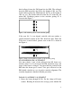
2. With help of two external mirrors Y1, Y2 direct attenuated
pump beam into amplifier through the center of the AM2 hole
onto the Ti:sapphire crystal surface (to the point where amplified
beams are intersected).
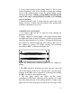
3. Place lens L1 into the pump beam maintaining the direction of
the pump beam. A distance from L1 to the TIS (approximately
680 mm) is determined by an initial diameter and divergence of
the pump beam. To find this distance watch with microscope a
diameter of the pump beam on the crystal surface. It should be
about 750 .
4. Set up concave mirror Y3, reflecting pumping beam back to
the Ti:sapphire crystal. A distance between the mirror and Ti:
sapphire crystal (approximately 205 mm) should be adjusted to
give reflected pump beam waist diameter about 750 inside the
crystal.
5. Switch-on „Q-switch” operation of the pump laser. Set pump
energy E
pump
= 20 mJ.