Model 25622 ➤Owner’s/Installation Guide
limited lifetime consumer warranty Directed Electronics (hereinafter "Directed") promises to the original purchaser to repair or replace with a comparable reconditioned Directed remote start unit if this Directed remote start unit (hereinafter "Unit"), excluding without limitation, any remote transmitters or associated accessories, proves defective in materials or workmanship under normal use for the life of the vehicle which the Unit is originally installed.
OR IN CONNECTION WITH THE INSTALLATION, USE, IMPROPER USE, OR INABILITY TO USE, THE PRODUCT, EVEN IF THE PARTY HAS BEEN ADVISED OF THE POSSIBILITY OF SUCH DAMAGES. SOME STATES DO NOT ALLOW THE EXCLUSION OF LIMITATION OF INCIDENTAL OR CONSEQUENTIAL DAMAGES, SO THE ABOVE LIMITATIONS OR EXCLUSION MAY NOT APPLY TO YOU. THE CONSUMER AGREES AND CONSENTS THAT ALL DISPUTES BETWEEN THE CONSUMER AND DIRECTED SHALL BE RESOLVED IN ACCORDANCE WITH CALIFORNIA LAWS IN SAN DIEGO COUNTY, CALIFORNIA.
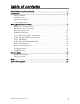
table of contents limited lifetime consumer warranty . . . . . . . . . . . . . . . . . . . . . . . . . . . . . . . . . . . . . . . . i Install Guide . . . . . . . . . . . . . . . . . . . . . . . . . . . . . . . . . . . . . . . . . . . . . . . . . . . . . . . . 3 what is included . . . . . . . . . . . . . . . . . . . . . . . . . . . . . . . . . . . . . . . . . . . . . . . . . . 3 installation tools . . . . . . . . . . . . . . . . . . . . . . . . . . . . . . . . . . . . . . . . . . . . . . . . . .
2 © 2006 Directed Electronics
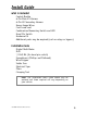
Install Guide what is included Control Module 6-Pin Main H1 Harness 6-Pin H2 Secondary Harness Heavy Gauge Wires Crash code card Combination Momentary Switch and LED Hood Pin Switch Hardware Kit Additional parts may be required (such as relays or bypass).
important information Congratulations on the purchase of your remote start system. This system is designed to integrate with your existing keyless entry or alarm system. Properly installed, this system will provide years of trouble-free operation. Please take the time to carefully read this User’s Guide in its entirety prior to installing your system. You can print additional or replacement copies of this manual by accessing the Directed web site at www.autocommand.com.
however, the following recommendations should be made to all users of this system: 1. Never operate the system in an enclosed or partially enclosed area without ventilation (such as a garage). 2. When parking in an enclosed or partially enclosed area or when having the vehicle serviced, the remote start system must be disabled by placing the system into Valet Mode. 3.
gear. OPERATION OF THE REMOTE START MODULE IF THE VEHICLE STARTS IN GEAR IS CONTRARY TO ITS INTENDED MODE OF OPERATION. OPERATING THE REMOTE START SYSTEM UNDER THESE CONDITIONS MAY RESULT IN PROPERTY DAMAGE OR PERSONAL INJURY. IMMEDIATELY CEASE THE USE OF THE UNIT AND REPAIR OR DISCONNECT THE INSTALLED REMOTE START MODULE. DIRECTED WILL NOT BE HELD RESPONSIBLE OR PAY FOR INSTALLATION OR REINSTALLATION COSTS.
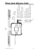
© 2006 Directed Electronics MOMENTARY SWITCH BLUE PINK GREEN (+) output to ign/acc2 circuit Heavy Gauge Wires H1 H2 Black (-) Heavy guage ground wire YELLOW/BROWN (-) 400mA Headlight output BROWN (-) 400mA RAP, Factory Alarm rearm YELLOW/GREEN (+) ignition output RED/BLACK (-) wait-to-start input BLUE (-) 400mA horn/siren output GREEN Tachometer input RED/WHITE (-) remote start activation WHITE/BLACK (-) 400mA status output ORANGE (+) brake input VIOLET (-) negative hood pin shutdown output
H1 Harness - 6 pin connector H1/1 ___ YELLOW H1/2 ___ BROWN/WHITE H1/3 ___ VIOLET H1/4 ___ ORANGE H1/5 ___ WHITE/BLACK H1/6 ___ RED/WHITE (+/-) parking light output (-) factory disarm output (-) hood pin shutdown input (+) brake switch shutdown input (-) 400mA status output (-) remote start activation input Pin # Color Note H1/1 Yellow Selectable positive or negative parking light output H1/2 Brown/White Use this wire if the vehicle is equipped with a factory alarm.
H2 Harness - 6 pin connector H2/1 ___ GREEN H2/2 ___ BLUE H2/3 ___ RED/BLACK H2/4 ___ YELLOW/GREEN H2/5 ___ BROWN H2/6 ___ YELLOW/BROWN Pin # Tachometer input (-) 400mA horn output (-) wait-to-start input (+) ignition output (-) 400mA RAP Output (-) 400mA headlight output Note H2/1 Color Green H2/2 Blue H2/3 Red/Black Negative output to horn circuit. If your horn is positive, use a relay. Used on diesel engines only.
relay heavy gauge wires 1 ___ GREEN 2 ___ PINK (+) 12 volt input 3 ___ BLUE (+) ignition 1 output 4 ___ WHITE 5 ___ PINK (+) 12 volt input 6 ___ YELLOW (+) starter output BLACK 10 (+) Ign2 or Acc2 output (+) accessory output (-) ground © 2006 Directed Electronics
Installation Overview Be sure to read this section thoroughly and in its entirety before starting the installation. Pay special attention to all warnings to prevent personal injury or damage to your vehicle. Visit our 24-hour technical web site (www.autocommand.com) to get a vehicle-specific wiring guide prior to starting this installation. Have your crash code number handy when contacting tech support or visiting the web site.
Step 1, Heavy Gauge Wire Connections Ground Wire The BLACK wire connects to the pin next to the light flash jumper fuse. First strip back a ¾-inch section of the insulation off the BLACK wire and crimp a ring terminal (not provided) to that wire. Locate a clean, paint-free metal surface in the drivers kick panel (do not ground on dash). Using a self-tapping screw, drill the screw with the ring terminal to the kick panel. Once screwed down, pull on the wire to ensure a good connection.
Once the lower dash panel has been removed, locate the ignition harness at the back of the key cylinder. This is usually a group of heavy gauge wires (approximate 14ga.). Place the black lead of the LED tester to a clean metal surface in the kick panel area and secure it. Probe one of the thicker gauge wires. The ignition wire colors of your specific vehicle can be obtained at www.autocommand.com.
With the key in the off position, test the suspect wire. The constant power wire will read 12V on the multimeter. Once the constant power wire has been identified, solder the two heavy gauge 12 VOLT wires (PINK) from the control module to it and wrap the connection with electrical tape. note! If the vehicle has more than one constant power wire, utilize two of them.
If your vehicle requires more than two ignitions, an additional relay (not provided) is required. Refer to the diagram below.
Accessory and Starter wires The starter and accessory wires will be located in the same harness as the ignition and constant power. To find the accessory wire leave the multimeter’s black lead connected to ground. Take the red lead and probe the wire suspected to be the accessory wire. With the key off, your multimeter should read 0 volts. Turn the key to the on position the multimeter should read 12 volts. Now turn the key to the crank position.
If the GREEN wire is being used for ign2 an additional relay (not provided) is required for a 2nd accessory. Refer to the diagram below.
Many Nissan and late-model Chrysler vehicles have two starter wires. A relay and/or resistor (not provided) is required to hook up the additional starter wire. Refer to the diagram below.
Step 2, H1, Main Harness Connections Factory Alarm Disarm Since many newer vehicles come equipped with a factory alarm it is necessary to disarm it during remote start. Do not mistake a factory alarm with an immobilizer system. They each require different disarm operations. Locate the factory alarm disarm wire using the web site information. Once the suspect wire is located, place the multi-meter's red lead to a (+)12 volt constant source and secure it.
Parking light flash There are several different types of parking light circuits. The following description is for a standard positive-triggered parkinglight circuit, only. If the web vehicle information suggests a (-) parking light circuit, the fuse jumper (on the side of the module) must be moved to the opposite position. The default position for this jumper is for a positive parking light circuit. Using the web information on the vehicle, locate the suspected wire.
Safety Shutdown Wires With all ignition wires properly connected, find the appropriate safety shutdown wires. These are the brake wire and hood pin wires. WARNING! These wires are meant to protect the vehicle and anyone near the vehicle. They MUST be connected to prevent damage to the vehicle and possible bodily injury. First locate the factory brake wire using your multimeter. Find the switch at the top of the metal arm coming off the brake pedal.
Using a sharp, pointed object poke a hole into the grommet (being careful not to damage any existing wires in the grommet) and attach the wire to the object with electrical tape. Pull the wire through the grommet taking extra care to keep the wire away from any moving parts or anything that will generate extreme heat. An alternative to this method would be to find a spot on the firewall with sufficient clearance on both sides and drill an access hole through the firewall.
Step 3, H2 Harness Engine Monitoring Explained During remote start the system will need to know if the engine is running. The module does this by monitoring the voltage of the vehicle's electrical system (or the tachometer-see next section). Voltage Monitoring note! If the system has been programmed for Tachometer monitoring previously, it must be reprogrammed to Voltage monitoring. Vehicle electrical systems usually rest at about 12.6 volts when the engine is not running.
Tachometer Wire WARNING! In the following procedure DO NOT use a test light. Use of this type of tester can cause grounding of sensitive electrical components causing damage, including damage to the power train control module. A digital multi-meter is required to test for this wire. Do not wear loose clothing that could get entangled in rotating engine components. Ensure that your hands and arms are well clear of these rotating components when working in the engine compartment.
of insulation off the tachometer wire in the vehicle and solder the green tachometer input wire to it. Then wrap the connection with electrical tape. note! If using a tach signal, the tach signal MUST be learned before using the remote starter. LEARNING YOUR TACH SIGNAL If using a tach wire, you must learn the tach signal after completing the installation. To learn tach signal: 1. Start car with key 2. Wait about 5 seconds for the engine to idle down 3.
Following is a brief description of the remainder of the wires in the H2 harness. For specific details on connecting these outputs contact Technical Support at 1-800-477-1382. Horn wire The Blue wire provides an output for activating the vehicle horn circuit during remote start. important! This is a low current output and that requires an external relay when connected to circuits that draw more than 400mA in current.
important! this is a low current output and that requires an external relay when connected to circuits that draw more than 400mA in current. Headlight Control wire The Yellow/Brown wire provides an output for activating the vehicle headlight circuit. It is programmable in Feature Menu 1/10 for the type of ignition controlled activation. important! this is a low current output and that requires an external relay when connected to circuits that draw more than 400mA in current.
Step 4, Immobilizer Bypass Modules Most newer vehicles have a factory engine immobilizer system designed to prevent any unauthorized use of the vehicle. These immobilizers will cut off power to the starter and the fuel supply preventing a thief from starting the vehicle. There are several types of immobilizers, with the most common being the resistance-based passlock/passlock 2 systems found on most newer GM vehicles.
Step 5, Programming Programming System Settings Many of the features and operations of this system can be changed to suit most of today's vehicle electrical systems. The programming routine and feature menus that follow will allow making the changes required for most vehicle installations. System programming routine: Accessing a Menu: 1. Turn the ignition ON and then OFF in less than 5 seconds 2. Within 3 seconds Press/Hold the Momentary Switch 3.
a. Option 1: The LED will turn ON and the Horn will pulse once. b. Option 2-4: The LED will flash and the Horn will pulse 2-4 times to indicate the option and the LED will continue to flash to indicate the option. Return to the beginning of the Menu: To return to the beginning of the menu at any time, press and hold the Momentary Switch for 2 seconds.
Feature Menu Feature Menu 1 Chart Feature Location Feature Name Option 1 (Default) Option 2 Option 3 Option 4 1 Engine Monitoring No Tach Tach NA NA 2 Run Time 15 min 30 min NA NA 3 Crank time Normal ExtraCrank Super crank Mega crank 4 Ign2 Output Ign 2 ACC 2 NA NA 5 Wait-to-start Diesel Input wire Diesel Timer NA NA 6 Activation Input 2 pulse 1 pulse NA NA 7 Vacation Temp 0 degrees F -10 degrees F -20 degrees F NA 8 Alarm Disarm 1 second 450 ms NA NA 9
Feature Menu 1 Descriptions 1. Engine Monitoring: Defines how the engine is monitored while the Remote Start is active. 1. No Tach: The battery voltage will be used to monitor the engine while Remote Start is active. 2. Tachometer: The tachometer will be used to monitor engine speed while Remote Start is active. 2. Run Time 1. 15 minutes: The Remote Starter will shut down after it has been active for 15 minutes. 2. 30 minutes: The Remote Starter will shut down after it has been active for 30 minutes. 3.
5. Wait-To-Start: This chooses the method of Starter output delay for Diesel engines. 1. Diesel Input wire: An input on the "Red/Blk" wire will delay the Start output until the input ceases. 2. Diesel Timer: The Starter output will be delayed 15 seconds. The "Red/Blk" wire will be ignored. 6. Activation Input: Selects the number of pulses on the "Red/Wht" activation input wire to activate the Remote Starter. 1. 2 Pulses: Two input pulse will Start and Stop the Remote Starter 2.
after an ignition input is sensed and cease output 1 second after the ignition input ceases. 2. LightYourWay: The output will activate for 25 seconds immediately after the ignition input ceases. 11. Start Chirps: Selects if the "Blue" Horn output wire will pulse when activating Remote Starter. 1. On: The Horn output will pulse 1 time at the beginning of Remote Start 2. Off: The Horn output WILL NOT pulse at the beginning of Remote Start 12. NA: A feature is Not Available for this Location 13.
Remote Start Diagnostics Remote Start Diagnostics: Remote Start diagnostics are an important tool that will diagnose the status of the remote start system by letting you know why it remote started, shut down or refused to start as expected. No Start Diagnostics: If the system fails to activate Remote Start, QuickStop, Daily Start or Vacation mode as expected the parking lights will flash to indicate the reason. Consult the No Start Diagnostic Chart for the reason.
Last Start Diagnostics: The system holds in memory the reason for the most recent remote start activation. This diagnostic report must be recalled using the following operation: 1. Turn the ignition ON and then OFF in less than 5 seconds 2. Within 5 seconds press and release the Momentary Switch 3. After 2 seconds the LED will flash/pause and repeat 5 times to indicate the cause of the most recent remote start activation. 4.
Shut Down Diagnostics: The system holds in memory the reason for the most recent remote start shut down. This diagnostic report must be recalled using the following operation: 1. Step on the foot brake and hold until Step 4 has begun 2. Turn the ignition ON and then OFF in less than 5 seconds 3. Within 5 seconds press and release the Momentary Switch 4. After 2 seconds the LED will flash/pause and repeat 5 times to indicate the cause of the most recent remote start shut down. 5.
Testing the system Neutral Safety Test Some vehicles do not have an electrical neutral safety switch. Instead, a mechanical neutral safety switch that physically interrupts the starter wire is used when the vehicle is in any drive gear. If the remote start is interfaced before this switch, it will provide protection from starting in gear. However, some vehicles combine the column shift mechanism and the mechanical neutral safety switch into one mechanical part.
rear of the vehicle because it may move slightly. 2. Make sure the hood is closed and there are no remote start shut-downs active. 3. Set the emergency brake. 4. Turn the key to the "run" position, this will release the shifter. 5. Place the shifter in the drive position. 6. Place your foot directly over the brake pedal, but do not depress it. Be ready to step on the brake if the starter engages. 7. Activate the remote start system. 8.
Remote Start Test Once steps 1-5 have been completed, the operation of the system can be tested. Ensure that the two 30-amp fuses are in the relay harness PINK wire fuse holders. Make sure that the vehicle is in park with the emergency brake on and the hood closed. Pulse the activation input wire 2 times to initiate the remote start function.
Troubleshooting ➜ The ignition comes on, but the starter will not crank. Does it start with the key in the ignition? If so, does the vehicle have an engine immobilizer? Does it start with the brake pedal depressed? (Make sure to disconnect the brake shutdown when performing this test.) If so, it may have a brake/starter interlock. Is the correct starter wire being energized? Check by energizing it yourself with a fused test lead. ➜ The starter cranks for 1 or 2-seconds but does not start.
Check to ensure that the hood is not open and that the brake pedal is not depressed. Check harnesses and connections. Make sure the harnesses are fully plugged into the remote start module. Make sure there are good connections to the vehicle wiring. Check voltage and fuses. Use a meter and check for voltage between the RED wire and the BLACK ground wire. If you have less than battery voltage, check both 30A fuses on the main power wires.
Model 25622 ➤Owner’s © 2006 Directed Electronics Guide 43
Owner’s Guide Now that the installation is complete and tested, it is time to learn about the many outstanding remote start features that are included in your system.
OPERATING YOUR SYSTEMS FEATURES The following Remote Start activation descriptions assume connection to the vehicle's factory keyless entry system or an aftermarket alarm. Your installer will inform you of the correct action for activating the Remote Starter. Remote Start Features Remote Start allows you to remotely start and run your vehicle for a programmed period of time.
note! If the lights flash more than once and the engine does not start, refer to the No Start Diagnostics for the cause. important! Never remote start your vehicle when the keys are in the ignition, except when activating Quick Stop Mode, and never start the vehicle if it is not in PARK and the Parking brake is not set. important! It is unsafe to operate a vehicle's motor in a garage or other closed off area. Breathing the exhaust from the vehicle is hazardous to your health.
Safety shut down inputs: While the vehicle is running during remote start operation, the system will monitor the vehicle and will automatically shut down the engine if the system receives any of the following shutdowns ➤ The brake pedal is pressed. ➤ The hood is opened. ➤ The programmed run time has elapsed. ➤ Low battery voltage ➤ High or low tachometer signal Quick Stop Mode The Quick Stop feature allows the vehicle to remain running after the key has been removed from the ignition.
➤ Exit the vehicle. ➤ The engine will run for the programmed run time or until a shut down input is activated. note! Quick Stop mode will not activate if the brake pedal is depressed. Daily Start The Daily Start feature will automatically start the engine 24 hours after it has been activated. This is convenient if you leave your house for work at the same time everyday. Simply activate as described 24 hours before you wish for the engine to start.
Vacation Mode Vacation mode is a valuable feature designed to maintain normal operating conditions when the vehicle is parked for extended periods. Vacation mode will monitor and automatically start the engine any time the system detects extremely low battery voltage or temperatures (See Programming Section for available low temperature settings). To activate Vacation Mode: ➤ With the Ignition off, press and release the Momentary ➤ ➤ ➤ ➤ Switch 5 times quickly.
Valet Mode Valet Mode will defeat the remote start operations. To enter Valet Mode: ➤ Press and hold the Momentary Switch ➤ Turn the ignition On and Off in less than 5 seconds ➤ Continue to hold the Momentary Switch ➤ After 2 seconds the LED will turn on solid, Valet Mode is entered note! The LED will stay on only when the ignition is off. After the ignition has been off for 24 hours the LED will turn off until the ignition is cycled on/off.
Glossary of terms Control Module: The “brain” of your system. Usually hidden under the dash area of the vehicle. It houses the microprocessor that monitors your vehicle and controls all system functions. FAD: Factory Alarm Disarm. Some vehicles with a factory alarm require the alarm to be disarmed before remote starting. RAP: Retained Accessory Power. After the vehicle is started and then shut down, the power to the radio remains on (retained) until a vehicle door is opened.
Notes _________________________________________________ _________________________________________________ _________________________________________________ _________________________________________________ _________________________________________________ _________________________________________________ _________________________________________________ _________________________________________________ _________________________________________________ _________________________________________________ ______
Remote Start the engine ■ To Start: Pulse the activation input wire twice. The engine will start and the parking lights will flash to confirm start. ■ To Stop: Perform the same steps as above to shut down remote start. Quick stop Mode ■ To activate: With the ignition on and the engine running, pulse the activation input wire twice or press/release the Momentary Switch 4 times ■ To de-activate: Pulse the activation input wire 2 times or step on the brake.
The company behind this system is Directed Electronics Since its inception, Directed Electronics has had one purpose, to provide consumers with the finest vehicle security and car stereo products and accessories available. The recipient of nearly 100 patents and Innovations Awards in the field of advanced electronic technology, DIRECTED is ISO 9001 registered. Quality Directed Electronics products are sold and serviced throughout North America and around the world.