Model 24923 Installation Guide © 2010 Directed Electronics, Vista, CA N24923 2010-08
Bitwriter®, Code Hopping™, Doubleguard®, ESP™, FailSafe®, Ghost Switch™, Learn Routine™, Nite-Lite®, Nuisance Prevention® Circuitry, Revenger®, Silent Mode™, Soft Chirp®, Stinger®, Valet®, Vehicle Recovery System®, VRS®, and Warn Away® are all Trademarks or Registered Trademarks of Directed Electronics.
Contents Important information ...................................................................................................................... 4 Installation tools ............................................................................................................................. 4 Installation overview ........................................................................................................................ 5 Wiring schematic ...................................................
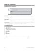
Important information Government Regulations and Safety information Read the Government Regulations and Warning! Safety First sections of this manual prior to operating this system. Warning! Failure to heed this information can result in death, personal injury or property damage and may also result in the illegal use of the system beyond its intended purpose. Guide Translations If you want a Spanish or French version of this expanded Installation guide, please download it from www.readyremote.
Installation overview Be sure to read this section thoroughly and view the Do-It-Yourself Installation DVD video that came with your system in its entirety before starting the installation. Pay special attention to all warnings to prevent personal injury or damage to your vehicle. Register at www.readyremote.com to gain access to our vehicle database where you can get specific installation information for your vehicle. If needed, additional hardware to support the features you want, is identified.
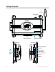
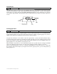
Wiring schematic Antenna Parking Light Jumper Top View H1 Primary Harness Side View H3 Auxiliary Harness Side View LED (Programming indicator) H2 Heavy Gauge Relay Control Button (Valet Switch) Door Lock/unlock Harness Antenna 6 © 2010 Directed Electronics. All rights reserved.
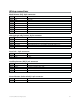
Wiring connections Main Harness (H1), 9-pin connector H1/1 LIGHT GREEN BLACK (-) 200mA FACTORY ALARM DISARM H1/2 GREEN/WHITE (-) 200mA FACTORY ALARM REARM H1/3 EMPTY NOT USED H1/4 WHITE/BLUE (-) ACTIVATION INPUT H1/5 EMPTY NOT USED H1/6 BROWN (-) 200mA HORN OUTPUT H1/7 RED/WHITE (-) 200mA TRUNK RELEASE (CHANNEL 2) OUTPUT H1/8 BLACK GROUND H1/9 WHITE (+/-) LIGHT FLASH OUTPUT Heavy gauge relay harness, 6-pin connector H2/1 PINK OUTPUT TO PRIMARY IGNITION CIRCUIT, 30A (+) H2/2 PU
Main harness (H1) connections Factory alarm disarm H1/1 LIGHT GREEN BLACK (-) 200mA FACTORY ALARM DISARM Since many newer vehicles come equipped with a factory alarm, it is necessary to disarm it when unlocking the doors or during remote start. Do not mistake a factory alarm with an immobilizer system. They each require different disarm operations. Locate the factory alarm disarm wire following instructions available on www.readyremote.com.
Ground wire H1/8 BLACK GROUND The BLACK wire connects to the pin next to the light flash jumper fuse. First strip back a ¾-inch section of the insulation off the BLACK wire and crimp a ring terminal (not provided) to that wire. Locate a clean, paint-free metal surface in the drivers kick panel (DO NOT GROUND ON DASH). Using a self-tapping screw, drill the screw with the ring terminal to the kick panel. Once screwed down, pull on the wire to ensure a good connection.
Heavy gauge relay harness (H2) Testing for Ignition Wires H2/1 PINK OUTPUT TO PRIMARY IGNITION CIRCUIT, 30A (+) With the multimeter lead still connected in the kick panel, locate the suspected ignition wire. It will test differently than constant 12 volts. Place the red lead of the multimeter on the suspected wire. With the key in the off position the multimeter will read 0. Turn the key to the on position and the multimeter will read 12 volts.
Accessory and starter wires H2/2 PURPLE OUTPUT TO STARTER CIRCUIT, 30A (+) H2/3 ORANGE OUTPUT TO ACCESSORY CIRCUIT, 30A (+) The starter and accessory wires will be located in the same harness as the ignition and constant power. To find the accessory wire, leave the multimeter’s black lead connected to ground. Take the red lead and probe the wire suspected to be the accessory wire. With the key off, your multimeter should read 0 volts. Turn the key to the on position The multimeter should read 12 volts.
Now that the accessories have been located, find the suspected starter wire according to the web information. Leave the black lead of your tester on ground and place the red lead of your multimeter on this wire. The multimeter should read 0 volts in all key positions except the crank position. In the crank position your multimeter should read 12 volts, and will go to 0 volts when the starter disengages. Many Nissan and Toyota vehicles have two starter wires.
Additional heavy gauge harness wire description H2/4 RED (+) 30A HIGH CURRENT 12V INPUT H2/6 RED (+) 30A HIGH CURRENT 12V INPUT Constant Power and Ignition Wires Almost all your power and ignition wires can be found behind the key cylinder under the lower driver's side dash panel. Using the appropriate hand tools, remove the lower dash panel taking care not to break any parts. If the panel does not come off easily, check for any additional screws you may have missed.
Auxiliary harness (H3) H3/1 BLACK/WHITE (-) NEUTRAL SAFETY SWITCH INPUT In most applications the neutral safety wire should be attached to a chassis ground. This does not apply to vehicles that crank the starter while the transmission is in gear. If your vehicle cranks the engine while the transmission is in gear you MUST call technical support at: 1-800-477-1382. H3/2 VIOLET/WHITE TACHOMETER INPUT WIRE Tachometer wire connections Caution! In the following procedure DO NOT use a test light.
Safety Shutdown Wires H3/3 BROWN (+) BRAKE SHUTDOWN INPUT WIRE H3/4 GRAY (-) HOOD PIN SWITCH SHUTDOWN WIRE With all ignition wires properly connected, find the appropriate safety shutdown wires. These are the brake wire and hood pin wires. Warning! These wires are meant to protect the vehicle and anyone near the vehicle. They MUST be connected to prevent damage to the vehicle and possible bodily injury. First locate the factory brake wire using your multimeter.
Door lock connections 1 LIGHT BLUE (-) UNLOCK 2 EMPTY NOT USED 3 GREEN (-) LOCK There are eight different types of door lock systems (Type A - H). Refer to the vehicle-specific wiring instructions on the web and the chart below to help determine which door lock system your vehicle uses. On some late model GM vehicles a door lock data interface module may be required. Type A: Three-wire (+) pulse controlling factory lock relays. Type B: Three-wire (-) pulse controlling factory lock relays.
Type A: Three-wire (+) pulse controlling factory lock relays The system can control Type A door locks directly, with no additional parts. The switch will have three wires on it; one will test (+)12 volt constantly. The others will alternately pulse (+)12 volt when the switch is pressed to the lock or unlock position. If you cannot get to the switch, and you find a set of wires that pulse (+)12 volt alternately on lock and unlock, make sure that it is not a Type C direct-wire system.
Type B: Three-wire (-) pulse controlling factory lock relays This system is common in many Toyotas, Nissans, Hondas, Saturns, and almost all newer Fords with keyless entry systems. Use your vehicle specific wiring information to locate this wire. If you cut the wire and the locks stop working, then you are on the correct wire.
Caution! If these wires are not connected properly, (+) 12 volts will be sent directly to (-) ground, possibly damaging the alarm or the factory switch. Type D: Adding one or more aftermarket actuators In order for this system to control one or more aftermarket actuators, a DEI 451M (not included) or two relays are required. Vehicles without factory power door locks require the installation of one actuator per door. This requires mounting the door lock actuator inside the door.
Type E: Electrically-activated vacuum systems Type E door locks are controlled by an electrically activated vacuum pump. Some Mercedes and Audis use a Type D system. Test by locking doors from the passenger key cylinder. If all the doors lock, the vehicle's door lock system can be controlled with just two relays (optional). The control wire can be found in either kick panel and will show (+)12 volt when doors are unlocked and (-) ground when doors are locked. To interface, see diagram below.
Type G: Positive (+) multiplex This system is sometimes found in Ford, Mazda, Chrysler, and GM vehicles. The door lock switch or door key cylinder may contain either one or two resistors. When interfacing with this type of door lock system, two relays or a DEI 451M must be used. Single-Resistor Type If one resistor is used in the door lock switch/key cylinder, the wire will pulse (+)12 volt in one direction and less than (+)12 volt when operated in the opposite direction.
Type H: Negative (-) multiplex The system is most commonly found in Chryslers and a few late-model GM vehicles. The door lock switch or door key cylinder may contain either one or two resistors. (See "Determining the Proper Resistor Values above) 22 © 2010 Directed Electronics. All rights reserved.
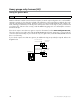
Mounting the antenna The antenna position should be discussed with the vehicle owner prior to installation, since the antenna may be visible to the vehicle’s operator. The best location for the receiver/antenna is centered high on either the front or rear windshield. For optimal range, the antenna should be mounted vertically. It can be mounted horizontally in relation to the windshield or under the dashboard away from metal, but range will be diminished.
Installation points Important: The LED mentioned in the installation section references the LED (programming indicator) on the Control Module, not on the remote control, unless otherwise stated. Engine/voltage monitoring During remote start, the system needs to know if the engine is running. The module does this by monitoring the voltage of the vehicle's electrical system (or the tachometer: see next section). Vehicle electrical systems usually rest at about 12.6 volts when the engine is not running.
Reset and deletion If a feature/Virtual Tach needs to be reset or the remote controls need to be deleted, use the following procedure. 1. Turn the ignition to the ON position (The heavy gauge pink wire must be connected). 2. Within 10 seconds, press and release the Control (Valet switch)button: 2 times if you want to delete remotes, 3 times to reset features or 4 times to reset Virtual Tach. These features are described next. Delete remotes: This feature erases all remotes from the system memory.
Remote start shutdown diagnostics If the remote start activates but fails to stay running, the remote start module has the ability to inform you of what may have caused the remote start failure. Before performing shutdown diagnostics it is important that you let the remote start shut off on its own i.e. let it attempt to start 3 times then shut down, if this is not done the unit will report the shutdown you used to shut off the remote start.
Programming system features The System Features Learn Routine dictates how the unit operates. It is possible to access and change most of the feature settings (see Feature Menus) using the Control (Valet Switch) button. 1. Turn the ignition on, then off. 2. Select a Menu. Press and hold the Control button. The number of LED flashes (on the control module) and horn honks* indicates the menu number. A single LED flash and honk indicates menu 1. Two LED flashes and 2 honks indicates menu 2. 3.
Feature menus Default settings are in bold type. Menu 1 Feature # Feature Opt. 1 Opt. 2 Opt. 3 Opt.4 Opt. 5+ 1 Horn function Off Siren 20 mS Siren 30 mS Siren 40 mS Siren 50 mS 2 Ignition controlled lock On Off 3 Ignition controlled unlock On Off 4 Doorlock output duration 0.8 sec. 3.5 sec.
when remote start is activated. 3. Remote start only: Factory Alarm Disarm wire will pulse as programmed during remote start only 8. Factory Alarm Disarm pulses 1. Single: Factory Alarm Disarm wire pulses once per operation 2. Double: Factory Alarm Disarm wire pulses twice per operation 9. Comfort Closure 1. Comfort Closure 1: door lock pulse (or 2nd pulse for double pulses) will remain on for 20 seconds. 2. No comfort Closure: Comfort Closure is defeated when locking 3.
Menu 2 Feature # Feature Opt. 1 Opt. 2 Opt. 3 Opt.4 1 Engine checking Virtual tach voltage Off tachometer 2 Remote Start Engine Runtime 12 min 24 min 60 min 3 Park light output Pulsed Constant 4 Cranking time 0.6 sec. 0.8 sec. 1.0 sec.
7. Accessory output 1. Off: the Accessory outputs will be OFF during diesel start delay. 2. On: the Accessory outputs will be ON during diesel start delay. 8. 2nd Status behavior 1. Normal : the output will activate before the ignition outputs turn on, and de-activate after they turn off during remote start. 2. Latch rear defogger: the output activates 10 seconds after start. It turns off after 10 minutes or upon remote start off. 3.
Troubleshooting: keyless entry Door locks operate backwards. • This unit has easily-reversed lock/unlock outputs. Recheck wire connections to see if you have reversed these. Troubleshooting: remote start The remote will not activate the remote start 1. Does the neutral safety input have a ground? if the wire is not grounded the remote start will not activate. 2. Have you performed the remote start shutdown diagnostics? Sometimes an active shutdown input will report in the diagnostics. 3.
4. Is an ignition or accessory output wire connected to the starter wire of the vehicle? Verify the color of the starter wire in the vehicle and confirm that an ignition or an accessory output is not connected to that wire. The vehicle starts, but will only run for 10 seconds 1. Is the remote start programmed for voltage sense? If this does not work, a tach wire should be used. 2. Check shutdown diagnostics. The climate control system does not work while the unit is operating the vehicle. 1.
Owner's Guide System maintenance The system requires no specific maintenance beyond battery replacement for the remote controls. Your remote is powered by a coin cell battery (3V CR2032) that lasts approximately one year under normal use. When the battery begins to weaken operating range is reduced. Battery replacement Locate the small slot on the side of the remote control. Insert a small slotted screwdriver or equivalent tool into slot and pry the case apart.
Using the System Note: Horn function is an programmable feature, it is Off by default. See Feature Menus and Programming System Features to turn on. Locking Pressing for one second locks the system (if the door locks are connected). The horn honks (see note) and the parking lights flash once to confirm the system is locked. Unlocking Pressing for one second unlocks the doors (if connected). The horn honks twice and the parking lights flash twice to confirm unlocking of the system.
While the vehicle is running during remote start operation, the system monitors the vehicle and automatically shuts down the engine if it receives any of the following shut-down inputs: • • • • • The brake pedal is pressed. The hood is opened. The shutdown toggle switch is put into the Off position. The pre-programmed run time (12, 24, or 60 minutes) has elapsed. is pressed once.
Government Regulations This device complies with Part 15 of FCC rules. Operation is subject to the following two conditions: (1) This device may not cause harmful interference, and (2) This device must accept any interference received, including interference that may cause undesirable operation. This equipment has been tested and found to comply with the limits for a class B digital device, pursuant to Part 15 of the FCC Rules.
Warning! safety first The following safety warnings must be observed at all times: • Due to the complexity of this system, installation of this product must be done properly according to instructions with safety always considered. • Failure to properly installed this system and its safety features may result in personal injurt, property damage or both. When properly installed, this system can start the vehicle via a command signal from the remote control.
Safety check Before vehicle reassembly, the remote system must be checked to ensure safe and trouble-free operation. The following test procedure must be used to verify proper installation and operation of the system. The installation must be completed before testing, including connection to the brake switch and hood switch. 1. Test the BRAKE shutdown circuit: With the vehicle in Park (P), activate the remote start system. Once the engine is running, press the brake pedal.
The company behind this system is Directed Electronics Since its inception, Directed Electronics has had one purpose, to provide consumers with the finest vehicle security and car stereo products and accessories available. The recipient of nearly 100 patents and Innovation Awards in the field of advanced electronic technology. DIRECTED is ISO 9001 Quality Directed Electronics products are sold and serviced throughout North America and around the world.