210D ➤Owner’s/Installation Guide
limited lifetime consumer warranty For a period of one calendar year from the date of purchase of this auto-security device, Directed Electronics, Inc.
TO THE MAXIMUM EXTENT ALLOWED BY LAW, ANY AND ALL WARRANTIES ARE EXCLUDED BY THE MANUFACTURER AND EACH ENTITY PARTICIPATING IN THE STREAM OF COMMERCE THEREWITH. THIS EXCLUSION INCLUDES BUT IS NOT LIMITED TO THE EXCLUSION OF ANY AND ALL WARRANTY OF MERCHANTABILITY AND/OR ANY AND ALL WARRANTY OF FITNESS FOR A PARTICULAR PURPOSE AND/OR ANY AND ALL WARRANTY OF NON-INFRINGEMENT OF PATENTS, IN THE UNITED STATES OF AMERICA AND/OR ABROAD.
table of contents limited lifetime consumer warranty . . . . . . . . . . . . . . . . . . . . . . . . . . . . . . . . . . . . . . . . i what is included . . . . . . . . . . . . . . . . . . . . . . . . . . . . . . . . . . . . . . . . . . . . . . . . . . . . . . 3 installation tools . . . . . . . . . . . . . . . . . . . . . . . . . . . . . . . . . . . . . . . . . . . . . . . . . . . . . . 3 important information . . . . . . . . . . . . . . . . . . . . . . . . . . . . . . . . . . . . . . . . . . . . . . . . .
diagnostics . . . . . . . . . . . . . . . . . . . . . . . . . . . . . . . . . . . . . . . . . . . . . . . . . . . . . . . . . 35 arming diagnostics . . . . . . . . . . . . . . . . . . . . . . . . . . . . . . . . . . . . . . . . . . . . . . 35 disarming diagnostics . . . . . . . . . . . . . . . . . . . . . . . . . . . . . . . . . . . . . . . . . . . . 36 system status chirps . . . . . . . . . . . . . . . . . . . . . . . . . . . . . . . . . . . . . . . . . . . . . . 37 table of zones . . . . . . . . . . . . .
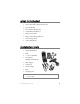
what is included ➤ On board Double Guard Shock Sensor ➤ Control Module ➤ Two 3-Button Transmitters ➤ 12-Pin Main H/1 Harness ➤ Plug-in Status LED ➤ Plug-in Valet®/Program Button ➤ 514 Revenger Siren ➤ Starter Kill Harness installation tools ➤ Digital Multi-Meter ➤ Drill ➤ 9 ➤ Screwdrivers /32 and 5/16 Drill Bits (Phillips and Flathead) ➤ Wire Stripper ➤ Solder Iron ➤ Electrical Tape ➤ Pliers ➤ Crimping Tool note: The installation tools required will vary depending on your v
important information Congratulations on the purchase of your security entry system. This system will allow convenient access to your vehicle with the push of a button, as well as other optional features. Properly installed, this system will provide years of trouble-free operation. Please take the time to carefully read this Owner’s/Install Guide in its entirety and watch the Rattler Do-It-Yourself Installation Video prior to installing your system.
➜ your warranty Your warranty registration must be completely filled out and returned within 10 days of purchase. Your product warranty will not be validated if your warranty registration is not returned. Please note that it is necessary to keep your proof of purchase. ➜ fcc/id notice This device complies with Part 15 of FCC rules.
primary harness (H/1), 12-pin connector 6 H1/1 ORANGE (-) 500 mA Ground-When-Armed Output H1/2 WHITE H1/3 WHITE/BLUE H1/4 BLACK/WHITE H1/5 GREEN H1/6 BLUE H1/7 VIOLET H1/8 BLACK H1/9 YELLOW (+) Ignition Input, Zone 5 H1/10 BROWN (+) Siren Output H1/11 RED H1/12 RED/WHITE (+) Light Flash Output (-) 200 mA Channel 3 Validity Output (-) 200 mA Dome light Supervision Output (-) Door Trigger Input, Zone 3 (-) Instant Trigger, Zone 1 (+) Door Trigger Input, Zone 3 (-) Chassis Ground I
installation Be sure to read this section thoroughly and view the Rattler DoIt-Yourself Installation Video in its entirety before starting the installation. Pay special attention to all warnings to prevent personal injury or damage to your vehicle. www.diyrattler.com) to get Visit our 24-hour technical Web site (w a vehicle-specific wiring guide prior to starting this installation.
➜ step 1 Plug-in LED and Valet®/Program switch The LED and the Valet®/Program switch both plug into the control module. The status LED plugs into the white two-pin port, while the Valet®/Program switch should be plugged into the blue two-pin port. The status LED and Valet®/Program switch each fit into 9/32-inch holes.
feed the wires through the hole and press the switch firmly until it snaps into place. Run the wires to the same location as the LED using caution to NOT run the wires near any moving objects or excessive heat. ➜ step 2 Ground Wire The BLACK wire on the main 8-pin harness is ground. This wire should be connected to a clean, paint-free area of metal in the drivers kick panel area. First strip back a ¾-inch section of the insulation off the BLACK wire and crimp a ring terminal (not provided) to that wire.
SELF-TAPPING BOLT OR SCREW GROUND WIRE DIA-591 NOTE: REMOVE ANY PAINT BELOW RING CONNECTOR RING CONNECTOR ➜ step 3 Constant Power and Ignition wires Almost all power and ignition wires can be found behind the key cylinder under the lower drivers side dash panel. Using the appropriate hand tools, remove the lower dash panel using care not to break any parts. If the panel does not come off easily check for any additional screws you may have missed.
thicker wires. With the ignition harness exposed, use your digital multi-meter to find your power and ignition wires. Place the black lead of the meter to a clean metal surface in the kick panel area and secure it. Put the meter in the DC voltage position, then take the red lead of the meter and probe one of the thicker gauge wires. The color and identity of your specific vehicle wiring can be obtained at www.diyrattler.com. With the key in the OFF position, test the suspect wire.
➜ step 4 Starter wire The starter wire will be located in the same harness as the ignition and constant power. Leaving the meter black lead connected to the metal ground. Find the wire suspected to be the starter wire according to the web information on your vehicle. Place the red lead of your meter on the wire. With the key in the off position the meter should read 0.00 volts and will stay at 0.00 volts in all key positions except the crank position.
Connect the BLACK starter kill wires as shown below. Use one of these wires as the starter kill input and the other as a starter kill output wire (these wires are interchangeable). ➜ step 5 Parking light flash There are several different types of parking light circuits. The following description is for a standard positive-triggered parking light circuit, usually located at the light switch.
important: While reading the meter turn (adjust) the dash dimmer control switch. The voltage should not vary on the meter. If the voltage does vary the incorrect suspected wire has been tested. Find the correct wire and retest. Once you have identified the correct wire, solder the WHITE wire on the main connector to it and cover the connection with electrical tape. ➜ step 6 Door triggers The door trigger is the circuit in the vehicle that tells the dome light to come on when the door is opened.
black lead of the meter and probe the suspect wire with the door open, you will see 11.00 to 13.00 volts appear on the meter, secure the black meter lead to the suspect wire and close the door with the display on the meter visible, if you have the right wire the voltage will drop to 0.00 volts, open the passenger door to verify that the wire sees both doors. Once confirmed solder the GREEN (H1/5) wire on the 12 pin harness to it and cover the connection with black tape.
➜ step 7 Dome light supervision (optional) The dome light wire is optional and not required for normal operation, however if desired you can have the security system turn on the dome light when the system is disarmed. If you would like this feature please refer to the web site or call technical support.
➜ step 9 Optional connections (channel 2, 3) When the system receives the code controlling channel 2, for longer than 1.5 seconds, the RED/WHITE wire (H1/12channel 2) will supply an output as long as the transmission continues. This is often used to operate a trunk/hatch release or other relay-driven function. When the system recieves the code controlling channel 3, the output is instantaneous, and the WHITE/BLUE wire (H1/3channel 3) will supply an output as long as the transmission continues.
➜ step 10 Hood/trunk pins The BLUE (H1/6) wire will respond to a negative input with an instant trigger. It is ideal for hood and trunk pins and will report on Zone 1. It can also be used with Directed Electronics 506T Glass Breakage Sensor, as well as other Directed Electronics single stage sensors. ➜ step 11 Adjusting the shock sensor note: The control module must be mounted in its permanent location before adjustments are made.
➜ step 12 Testing the system With all the previous steps completed, the operation of the system can now be tested. ■ Close all the doors and press the button on the transmitter, the system should chirp one time. ■ At this point the system will go through diagnostics, a 15 second process in which the security system will analyze the status of all connected zones.
work correctly check your wiring against the manual and verify all connections. If you still are experiencing problems contact Rattler technical support. note: If the shock sensor does not operate as described, see the Shock sensor adjustment section of this guide. transmitter functions The receiver uses a computer-based learn routine to learn the transmitter buttons. This makes it possible to assign any specific transmitter button, or combination of buttons, to any receiver function.
➜ standard configuration Button The arm/disarm function is controlled by pressing . Button This channel 2 accessory is used for trunk release. Button This channel 3 accessory is an additional channel for optional accessory functions such as remote start. © 2003 directed electronics, inc.
transmitter/receiver learn routine The system comes with 2 transmitters that have been taught to the receiver. The receiver can store up to 4 different transmitter codes in memory. Use the following learn routine to add transmitters to the system or to change button assignments if desired. The Valet®/Program switch, plugged into the blue port, is used for programming. There is a basic sequence of steps to remember whenever programming this unit: Door, Key, Choose, Transmit and Release. 1.
3. Choose. Within 10 seconds, press and release the Valet®/Program switch the number of times for the desired function. Then press the switch once more and hold it. The siren will chirp and the LED will flash to confirm the selected channel. Do not release the Valet®/Program switch. Channel number Function 1 Auto Learn 2 Arm/Disarm 3 Channel 2 Output 4 Channel 3/Remote Start 5 Delete all Transmitters 4. Transmit.
Auto Learn function This function provides a 1–step programming of the transmitter to the following factory default settings: ➤ Button —Lock/Unlock ➤ Button —Channel 2 output ➤ Button —Channel 3/Instant output note: All programmable features will be reset to factory default settings. Delete all Transmitters In case the transmitter(s) is lost or stolen, this function provides removal of all transmitter(s) access from the system memory. Learn Routine will be exited if: ➤ The doors are closed.
operating settings learn routine Many of the operating settings of this unit are programmable. They can be changed whenever necessary through the Operating Settings Learn Routine™. The Valet®/Program push-button switch, plugged into the blue port, is used together with a programmed transmitter to change the settings. To enter the System Features Learn Routine™: 1. Open a door. (The GREEN wire, H1/5, or the VIOLET, H1/7 must be connected.) 2. Ignition. Turn the ignition on, then back off.
Transmit. While HOLDING the 4. Valet /Program switch, you can select the ® desired feature settings using the remote transmitter. Pressing Button while HOLD - ING down the Valet /Program switch will program the feature ® to the LED ON settings. The siren will chirp once to indicate the one-chirp setting has been selected. Pressing Button while HOLDING down the Valet®/Program switch will change the setting to the LED OFF setting.
4. The siren will chirp two times to confirm that you have accessed Feature 2, Confirmation Chirps. ➜ to exit the learn routine To exit the learn routine, do one of the following: 1. Close the open doors. 2. Turn the ignition on. 3. No activity for longer than 15 seconds. 4. Press the Valet®/Program switch at least 9 times. © 2003 directed electronics, inc.
features menu The factory defaults are indicated in bold text in the table below. Feature Number Default LED On Setting (press transmitter button 1) LED Off Setting (press transmitter button 2) 1 Active Arming Passive Arming 2 Confirmation chirps ON Confirmation chirps OFF 3 No Feature 4 No Feature 5 No Feature 6 No Feature 7 Code Hopping ON Code Hopping OFF note: The number in parentheses indicate the number of times the LED will flash. The Factory defaults are indicated in bold type.
feature descriptions 1 ACTIVE/PASSIVE ARMING: When active arming is selected, the system will only arm when the transmitter is used. When set to passive, the system will arm automatically 30 seconds after the last door is closed. Passive arming is indicated by the rapid flashing of the LED when the last protected entry point is closed. 2 CONFIRMATION CHIRPS ON/OFF: This feature controls the chirps that confirm the arming and disarming of the system.
using your system ➜ arming with transmitter Pressing for one second will arm the system. The parking lights will flash once and the siren will chirp once to confirm that the system is armed. ➜ arming without a transmitter The security system also can be programmed to arm itself without a transmitter (called passive arming).
➤ ➤ Heavy impacts will trigger the system. The triggered sequence is 30-seconds of constant siren sounding and flashing parking lights. If a protected entry (door, hood, or trunk) is opened, the system will immediately trigger the siren and flash the parking lights. The hood and trunk are instant alarm triggers. The door is a progressive trigger (a series of rapid chirps for a few seconds before the alarm sounds). The progressive trigger allows time for you to disarm of the system prior to the alarm.
➜ disarming without a transmitter If your remote transmitter is lost or damaged, you can manually disarm your vehicle security system. To disarm the system without a transmitter, you must have the vehicle's ignition key and know where the Valet®/Program switch is located. Be sure to check with your installer at the time of installation for its location. To disarm the security system: 1.Turn the ignition key on. DRW-35 2.Press the Valet®/Program switch within 15 seconds. The system will now disarm.
will flash for 30-seconds. To stop the Panic Mode at any time, press again. ➜ silent mode Use the Silent Mode to temporarily turn off the arm or disarm chirps by briefly pressing before pressing the when arming or disarming. The confirmation chirp(s) will then be eliminated for that one operation only. To permanently turn off the arm and disarm chirps, see the programming section of this guide. note: The Warn Away Response to lighter impacts is bypassed if the system is armed using the Silent Mode.
➜ manual valet mode To enter or exit Valet Mode with the Valet®/Program switch: 1. Turn the ignition on. 2. Turn the ignition off. 3. Press and release the Valet®/Program switch DRW-35 within 10 seconds. The status LED will light steady if you are entering Valet Mode and will turn off if you are exiting Valet Mode. ➜ remote valet You can also enter or exit Valet Mode by using the remote transmitter: 1. Open any vehicle door. 2. Press . 3. Press . 4. Press again.
diagnostics The microprocessor at the heart of your system has the ability to constantly monitor all of the switches and sensors connected to it. It can detect any faulty switches or sensors and prevent them from disabling the entire system. It can also record and report any triggers that occur when you are away from your vehicle. ➜ arming diagnostics If the system is armed at the same time that an input is active (door opening, sensor triggering, etc.
➜ disarming diagnostics Your system has a Tamper Alert feature that notifies you of system triggers that occur while you are away from your vehicle. If you hear four chirps when you disarm, this indicates that the system was triggered in your absence. If you hear five chirps when you disarm, this indicates that a specific zone was triggered so many times that the NPC™ has bypassed that zone. In both cases, the pattern of the flashing status LED indicates which zone was triggered (see Table of Zones).
➜ system status chirps ACTION NUMBER OF CHIPS Arm 1 Arm 1 (3-second delay), 1 DESCRIPTION System armed System armed with Bypass Notification Disarm 2 System disarmed Disarm 4 System disarmed with Tamper Alert Disarm 5 System disarmed NPC® active © 2003 directed electronics, inc.
➜ table of zones A zone is represented by the number of LED flashes used by the system to identify a particular type of input. Standard input assignments are listed in the following table, along with spaces to write in any optional sensors or switches that you have had installed.
interprets this pattern of triggers as false alarms. After the third trigger, the NPC™ ignores, or bypasses, that sensor or switch (along with any other sensors or switches sharing the same zone) for 60 minutes. If the bypassed sensor is triggered again while it is already being bypassed, the 60-minute bypass period will start over. This ensures that a sensor that is continually being triggered will remain bypassed. The vehicle doors are protected differently by NPC™.
code hopping ™ re-synchronize If the transmitter is pressed many times out of range, or the battery is removed, the transmitter may get temporarily out of synchronization and fail to operate the system. To synchronize he transmitter, simply press several times within range of the vehicle. The system will automatically synchronize and the transmitter will respond normally. troubleshooting ➤ Door input does not immediately trigger full alarm.
Are the door inputs connected? Is the H1/6 blue wire connected to the door trigger wire in the vehicle? Either the H1/5 green or the H1/7 violet should be used instead. (See Primary Harness Wire Connection Guide section of this guide.) ➤ Door input does not respond with the progressive trigger, but with immediate full alarm: Does the Status LED indicate that the trigger was caused by the shock sensor? (See Table of Zones section of this guide.
glossary of terms Control Module: The "brain" of your security system. Usually hidden underneath the dash area of the vehicle. It houses the microprocessor that monitors your vehicle and controls all of the security system’s functions. Failsafe ® Starter Kill Relay: Located on-board the control module, this is an automatic switch controlled by the security system that prevents the vehicle's starter from cranking whenever the system is armed.
Transmitter: A hand-held, remote control that operates the various functions of the security system. Trigger or Triggered Sequence: The "setting off" or "tripping" of the alarm. A Triggered Sequence consists of the siren sounding and the parking lights flashing for 30 seconds. Valet®/Program Switch: A small, push-button switch mounted inside the vehicle, at a location determined by the installer.
security & convenience expansions Listed below are some of the many expansion options available for use with your system. Some options may require additional parts and/or labor. Please consult with your dealer for a complete list of options available for use with this system. Audio Sensor: Metal on glass, glass cracking, and breaking glass produce distinctive acoustic signatures.
Power Window Control: Automatic power window control is provided with the 529T and 530T systems. These options operate power windows, by rolling them up, down, or both up and down. The 530T also offers one-touch switch operation.
wiring quick reference diagram 46 © 2003 directed electronics, inc.
notes _________________________________________________ _________________________________________________ _________________________________________________ _________________________________________________ _________________________________________________ _________________________________________________ _________________________________________________ _________________________________________________ _________________________________________________ _________________________________________________ ______
48 © 2003 directed electronics, inc.
✂ ✂ To arm the system using your remote ■ Pressing for one second will arm the system. The parking lights will flash once and the siren will chirp once. To disarm the system using your remote ■ To disarm the system, press for one second. The parking lights will flash twice and the siren will chirp twice to confirm the system is disarmed. To enter panic mode using your remote ■ Press for 1.5 seconds. The parking lights will flash and the siren will sound for 30 seconds.
50 © 2003 directed electronics, inc.
© 2003 directed electronics, inc.
The company behind this system is Directed Electronics, Inc. Since its inception, Directed Electronics has had one purpose, to provide consumers with the finest vehicle security and car stereo products and accessories available. The recipient of nearly 100 patents and Innovations Awards in the field of advanced electronic technology, DIRECTED is ISO 9001 registered. Quality Directed Electronics products are sold and serviced throughout North America and around the world.