
Operating instructions
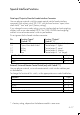


Pin Assignment Chart
Female Interface Connector:
25-position D-submini, DB25S, with screw lock hardware for cable gland
Male Connector Required: (please use connectors with the same specifications)
25-pin D-submini, DB25S, with shielded cable clamp assembly
(Amp type 826 985-1C) and fastening screws (mate screws for female screw lock,
Amp type 164 868-1)
Pin Assignment:
Pin 1: Signal Ground
Pin 2: Data Output (T×D)
Pin 3: Data Input (R×D)
Pin 4: “Signal Return” (T× D/R ×D)
Pin 5: Clear to Send (CTS)
Pin 6: Internally Connected
Pin 7: Internal Ground
Pin 8: Internal Ground •••••
Pin 9: Reset _ In**)
Print/ Open/Close f Key/ F Key/ Tare/
Pin 10: –12 V
Universal Draft Shield Control Control Control
Pin 11: +12 V
Switch*) Control Output 2*) Output 3*) Output 4*)
Pin 12: Reset _ Out**)
Output 1*)
Pin 13: +5 V
Pin 14: Internal Ground
Pin 15:
Pin 16:
Pin 17:
Pin 18:
Pin 19:
Pin 20: Data Terminal Ready (DTR)
Pin 21: Supply Voltage Ground “COM”
Pin 22: Not Connected
Pin 23: Not Connected
Pin 24: Supply Voltage Input +15..25 V
Pin 25: +5 V
*) = to change the pin assignment, see “Data Input/Output to/from the
Female Interface Connector” on page 4–17
**) = hardware restart
4–19