® Model 552 Installation Guide ® © 1999 Directed Electronics, Inc. Vista, CA N552A 12-99 Downloaded from: http://www.guardianalarms.
table of contents What Is Included . . . . . . . . . . . . . . . . . . . . . 3 Plug-in LED and Valet®/Program Switch . . . . . 23 Warning! Safety First . . . . . . . . . . . . . . . . . . 4 Harness 4, (+/-) Door Lock Outputs Type A . . . . . . . . . . . . . . . . . . Type B . . . . . . . . . . . . . . . . . . Type C . . . . . . . . . . . . . . . . . . Type D . . . . . . . . . . . . . . . . . . Type E . . . . . . . . . . . . . . . . . . Type F . . . . . . . . . . . . . . . . . .
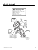
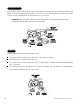
what is included ■ ■ ■ ■ ■ ■ ■ The control module (see diagram) Two 476A remote transmitters The plug-in status LED The Plug-in Valet®/Program switch A hood pinswitch A relay satellite A toggle override switch 6-pin mini molex plug Removable door for internal programming 3-pin 2-wire Door Lock Harness 3-pin Program Port 2-pin mini blue Valet®/ Program plug 2-pin micro LED plug © 1999 Directed Electronics, Inc.
warning! safety first The following safety warnings must be observed at all times: ■ Due to the complexity of this system, installation of this product must only be performed by an authorized DEI dealer. ■ When properly installed, this system can start the vehicle via a command signal from the remote control transmitter. Therefore, never operate the system in an area that does not have adequate ventilation.
installation points to remember IMPORTANT! This product is designed for fuel-injected, automatic transmission vehicles only. Installation of this product in a standard transmission vehicle is dangerous and is contrary to the product's intended use. Do not disconnect the battery if the vehicle has an anti-theft-coded radio. Also avoid disconnecting the battery if the vehicle is equipped with an airbag. Many airbag systems will display a diagnostic code through their warning light after they lose power.
valet/program switch Ensure that the location you pick for this switch has sufficient clearance to the rear. The switch should be well hidden. It should be placed so that passengers or stored items (such as items placed in a glove box or center console) cannot accidentally bump it. The switch fits in a 9/32-inch hole. IMPORTANT! When the vehicle is delivered, please show the user where the Valet®/Program switch is located and how to disarm the system using the switch.
starter kill relay If the starter kill relay or its connections are immediately visible upon removal of the under-dash panel, they can easily be bypassed. Always make the relay and its connections difficult to discern from the factory wiring! Exposed yellow butt connectors do not look like factory parts, and will not fool anyone! For this reason, routing the starter kill wires away from the steering column is recommended.
finding the 12V switched ignition wire The ignition wire is powered when the key is in the run or start position. This is because the ignition wire powers the ignition system (spark plugs, coil) as well as the fuel delivery system (fuel pump, fuel injection computer). Accessory wires lose power when the key is in the start position to make more current available to the starter motor. How to find (+)12V ignition with your multimeter: 1. Set to DCV or DC voltage (12V or 20V is fine). 2.
finding a (+/-) parking light wire Most vehicles use a (+) parking light circuit. The (+) parking light wire is often found near the light switch. In many vehicles the light switch is built into the turn signal lever; in these vehicles the parking light wire can be found in the steering column. The same wire can often be accessed in the kick panel or running board. NOTE: Many Toyotas and other Asian vehicles, send a (-) signal from the switch to a relay. The relay then sends (+)12V to the bulbs.
finding the accessory wire An accessory wire will show +12V when the key is in the accessory and run positions. It will not show +12V during the cranking cycle. There will often be more than one accessory wire in the ignition harness. The correct accessory wire will power the vehicle's climate control system. Some vehicles may have separate wires for the blower motor and the air conditioning compressor. In such cases, it will be necessary to add a relay to power the second accessory wire.
wiring the control unit The wiring harness supplied with this unit is the standard 12-pin harness used by DEI® security systems. Three wires in the plug are not used. The upgrade from this unit to a security system would simply require unplugging and exchanging control units and connecting the necessary wires to the vehicle. The functions of all the wires that are used in the primary harness are displayed in the following wiring diagram and their connections are described in the wire connection guides.
heavy gauge relay satellite wiring diagram 1 2 3 4 5 6 ______ ______ ______ ______ ______ ______ RED (+) HIGH CURRENT 12V INPUT RED (+) HIGH CURRENT 12V INPUT PINK (+) OUTPUT TO IGNITION CIRCUIT ORANGE (+) OUTPUT TO ACCESSORY CIRCUIT PURPLE (+) OUTPUT TO STARTER CIRCUIT PINK/WHITE (+) OUTPUT TO SECOND IGNITION CIRCUIT (H2) harness auxiliary connector wiring diagram H2/1 H2/2 ______ ______ GRAY/BLACK (-) WAIT-TO-START INPUT LIGHT GREEN/BLACK (-) FACTORY DISARM/SPECIAL ACCESSORY remote sta
primary harness (H1), 8-pin connector H1/1 ORANGE (-) ground-when-armed output This wire supplies a (-) 500 mA ground as long as the system is armed. This output ceases as soon as the system is disarmed. The orange wire is pre-wired to control the 8618 starter kill relay. NOTE: If connecting the orange wire to control another module, such as a 529T or 530T window controller, a 1 amp diode (type 1N4004) will be required. Insert the diode as shown below.
H1/3 WHITE/BLUE (-) activation input Sending a negative pulse to this wire will initiate the remote start sequence. This wire can be wired to an optional momentary switch to activate the remote start system. H1/4 BLACK /WHITE (-) 200 mA domelight supervision output Connect this wire to the optional domelight supervision relay as shown below: IMPORTANT! This output is only intended to drive a relay.
H1/10 BROWN (-) horn honk output This wire supplies a 200 mA (-) output that can be used to honk the vehicle horn. It outputs a single pulse when locking the doors with the remote, and two pulses when unlocking with the remote. This wire will also output pulses for 30 seconds when the Panic Mode is activated. If the vehicle has a (+) horn circuit, an optional relay can be used to interface with the system, as shown below.
relay satellite key switch interface The five heavy gauge wires leading from the relay satellite are used to energize high current circuits in the vehicle. It is crucial that these connections are made correctly so that they are capable of handling the current demands. For this reason, scotch locks, T-taps and other such connectors should not be used.
harness 2 (H2), 2-pin auxiliary plug H2/1 GRAY/BLACK (-) diesel wait-to-start bulb input Connect this wire to the wire in the vehicle that sends the signal to turn on the WAIT-TO-START bulb in the dashboard. In most diesels the wire is negative (ground turns on the bulb) and the GRAY/BLACK can be directly connected to the wire in the vehicle. If the vehicle uses a positive wire (12V to turn on the bulb) a relay must be used to change the polarity. (See Finding the Wires You Need section of this guide.
H2/2 LIGHT GREEN/BLACK (-) auxiliary output This wire sends a negative pulse every time the remote start is activated. This can be used to pulse the disarm wire of the vehicle's factory anti-theft device. Use a relay to send a (-) or (+) pulse to the disarm wire as shown in the diagrams below. This wire can also be used as a special accessory output. (See Feature Descriptions section of this guide.
H3/3 GRAY (-) hood pinswitch input This wire MUST be connected to hood pinswitch. This input will disable or shut down the remote start when the hood is opened. H3/4 BROWN (+) brake switch input This wire MUST be connected to the vehicle's brake light wire. This is the wire that shows (+) 12V when the brake pedal is depressed. The remote start will be disabled or shut down any time the brake pedal is depressed.
neutral safety switch interface Some vehicles combine the column shift mechanism and the mechanical neutral safety switch into one mechanical part. In these vehicles, it is impossible to interface the remote start system before the neutral safety switch. With this type of vehicle, if the vehicle is left in a drive gear and the remote start system is activated, the vehicle will move and may cause damage to persons or property.
IMPORTANT! Once the interface is complete, attempt to remote start the vehicle with the door closed and the key in the ignition. The vehicle should not start. If it does, re-check the connections. As of the date of this guide’s publication, the following list describes the types of vehicles that are known to have a mechanical neutral safety switch instead of an electrical neutral safety circuit. The model years will vary from vehicle to vehicle.
pre-1996 dodge dakota pickups with 2.5 liter motors 22 © 1999 Directed Electronics, Inc.
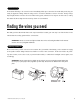
plug-in LED and valet/program switch These plug into the module. The status LED plugs into the small two-pin socket, while the Valet®/Program switch should be plugged into the larger blue two-pin connector. The status LED fits in a 9/32-inch hole.
type A: (+) 12V pulses from the switch to the factory relays The system can control this type of system directly, with no additional parts. The switch will have three wires on it, and one will test (+)12V constantly. The others will alternately pulse (+)12V when the switch is pressed to the lock or unlock position. If you cannot get to the switch, and you find a set of wires that pulse (+)12V alternately on lock and unlock, you must take care to ensure that it is not a Type C direct-wire system.
type B: (-) pulses from the switch to the factory relays This system is common in many Toyota, Nissan, Honda, and Saturn models, as well as Fords with the keyless-entry system (some other Fords also use Type B). The switch will have three wires on it, and one wire will test ground all the time. One wire will pulse (-) when the switch locks the doors, and the other wire will pulse (-) when the switch unlocks the doors. This type of system is difficult to mistake for any other type.
type C: reversing polarity Interfacing with a reversing polarity system requires either two relays or one 451M Door Lock Relay Satellite (not included). It is crucial to identify the proper wires and locate the master switch to interface properly. Locate wires that show voltage on lock and unlock. Cut one of the suspect wires and check operation of the locks from both switches.
type D: aftermarket actuators In order for this system to control one or more aftermarket actuators, a 451M Door Lock Relay Satellite (optional) or two relays (optional) are needed. Vehicles without factory power door locks require the installation of one actuator per door. This requires mounting the door lock actuator inside the door. Other vehicles may only require one actuator installed in the driver's door if all door locks are operated when the driver's lock is used.
type E: mercedes-benz and audi (1985 and newer) These door locks are controlled by an electrically activated vacuum pump. Some Mercedes and Audis use a Type D system. Test by locking doors from the passenger key cylinder. If all the doors lock, the vehicle's door lock system can be controlled with just two relays (optional). The control wire can be found in either kick panel and will show (+)12V when doors are unlocked and (-) ground when doors are locked. To interface, see the diagram below.
internal programming jumpers Tach Threshold OFF (+) Light Flash Output Tach Threshold ON (-) Light Flash Output light flash jumper This jumper is used to determine the light flash output polarity. In the (+) position, the on-board relay is enabled and the unit will output (+)12V on the WHITE wire, H1/2. In the (-) position, the on-board relay is disabled. The WHITE wire, H1/2, will supply a 200mA (-) output suitable for driving factory parking light relays.
transmitter/receiver learn routine The system comes with two transmitters that have been taught to the receiver. The receiver can store up to 4 different transmitter codes in memory. Use the following learn routine to add transmitters to the system or to change button assignments if desired. Using the optional DEI® Bitwriter™ or PC Interface, the learn routine may be locked. Make sure the learn routine is unlocked before programming features.
system's memory. It can also be used to start from scratch if the transmitter buttons were programmed incorrectly. 3. Transmit. While holding the Valet®/Program switch, press the button on the transmitter that you would like to control the selected receiver channel. The unit will chirp to confirm that the code has been successfully programmed. It is not possible to teach a transmitter button to the system more than once. 4. Release. Once the code is learned, the Valet®/Program switch can be released.
tach learning to learn the tach signal 1. Start the vehicle with the key. 2. Within 5 seconds, press and hold the Valet/Program switch. 3. The LED will light constant when the tach signal is learned. 4. Release the Program switch. DRW-96 operating settings learn routine The System Features Learn Routine™ dictates how the unit operates. Due to the number of features, the features have been divided into two menus.
to program the learn routine 1. Key. Turn the ignition on and then back off. 2. Select Menu. Press and hold the Valet®/Program switch until either the LED flashes once and the horn honks once to select Menu One, or the LED flashes twice and the horn honks twice to select Menu Two. 3. Choose. Within 10 seconds, press and release the Valet®/Program switch the number of times corresponding to the feature number you want to program. (See Feature Menus.
to exit the learn routine t The learn routine will be exited if: ■ The ignition is turned on. ■ The Valet/Program switch is pressed too many times. ■ More than 15 seconds elapses between programming steps. One long horn honk (if connected) indicates that the Learn Routine has been exited.
menu #2 FEATURE NUMBER DEFAULT - LED ON SETTING (PRESS CHANNEL 1) LED OFF SETTING (PRESS CHANNEL 2) 2-1 Engine checking on Engine checking off 2-2 Tachometer checking type Voltage checking type 2-3 12 minutes run time 24 minutes, 60 minutes run time 2-4 Flashing parking light output Constant parking light output 2-5 Cranking time 0.6 sec. (1)* Cranking time 0.8 (2), 1.0 (3), 1.2 (4), 1.4 (5), 1.6 (6), 1.8 (7), 2.0 (8), 4.0 (9) sec.
1-5 DOOR LOCK PULSE DURATION: Some European vehicles, such as Mercedes-Benz and Audi, require longer lock and unlock pulses to operate the vacuum pump. Programming the system to provide 3.5 second pulses will accommodate the door lock interface in these vehicles. The default setting is 0.8 second door lock pulses. 1-6 DOUBLE PULSE UNLOCK OFF/ON: Some vehicles require two pulses on a single wire to unlock the doors.
2-2 TACH WIRE SENSE/VOLTAGE SENSE: If the tachometer signal wire is used, this feature must be left in the default (tach wire connected) setting. If programmed to the voltage sense setting, the unit will crank the starter for a preset time that can be programmed in Feature 5. Once the starter has been engaged, the system will check the voltage level to verify the engine is running. The threshold for the voltage level test can be programmed in Feature 2-6.
shutdown diagnostics The unit has the ability to report the cause of the last shutdown of the remote start system. to enter diagnostic mode 1. Turn the ignition off. 2. Press and hold the Valet/Program switch. 3. Turn the ignition on and then off. 4. Release the Valet/Program switch. 5. Press and release the Valet/Program switch.
valet mode to enter or exit valet mode To enter or exit Valet® Mode with the Valet®/Program switch: 1. Turn the ignition on and then off. 2. Within 10 seconds, press and release the Valet®/Program switch. The status LED will light solid if you have entered Valet® Mode, and will go out if you have exited Valet® Mode. timer mode This unit can be programmed to start and run the engine every three hours. The engine will run for the programmed run time and then shut down.
to exit timer mode manually Timer Mode can also be exited manually as follows: 1. Make sure the remote start system is not operating the engine. 2. Turn the ignition on. Timer Mode will be exited and the parking lights will flash four times. safety check Before vehicle reassembly, the remote system must be checked to ensure safe and trouble-free operation. The following test procedure must be used to verify proper installation and operation of the system.
■ If the starter does not engage, the test is complete. Once the system passes the three tests, the vehicle can be re-assembled and delivered. Do not the use the remote start system or finalize the installation if it fails any of the safety check tests. troubleshooting ■ The ignition comes on, but the starter will not crank.
■ The remote start will activate but the starter never engages. 1. Check for voltage on the purple starter wire two seconds after the remote start becomes active. If there is voltage present, skip to Step 4. If there is not voltage present, advance to Step 2. 2. Check the 30A fuses. 3. Check diagnostics. If the gray/black wire is detecting ground upon activation, the starter will not crank. 4. Make sure the purple starter wire is connected on the starter side of the starter kill relay. 5.