Matrix RSIII Installation Guide © 2003 Directed Electronics, Inc.
The Bitwriter® (p/n 998T) requires chip version 1.4 or newer to program this unit. www.directechs.com DirectFax 800-999-1329 Technical Support 800-753-0800 These resources are for authorized Directed Dealer use only. This device complies with Part 15 of FCC rules. Operation is subject to the following conditions: (1) This device may not cause harmful interference, and (2) This device must accept any interference received, including interference that may cause undesired operation.
Table of Contents Warning! Safety First .................................4 Installation Points to Remember ................5 Before Beginning the Installation...........5 Finding the Tachometer Wire ...............5 Finding the WAIT-TO-START Bulb Wire for Diesels .....................................6 After the Installation ..............................6 Vehicle Anti-Theft Systems (Immobilizers) .......................................6 Primary Harness (H1) Wire Connection Guide ............................
Warning! Safety First Due to the complexity of this system, installation of this product must only be performed by an authorized Directed dealer. ➤ When properly installed, this system can start the vehicle via a command signal from the transmitter/receiver. Therefore, never operate the system in an area that does not have adequate ventilation.
Installation Points to Remember Before Beginning the Installation IMPORTANT! This product is designed for fuel-injected, automatic transmission vehicles only. Installing it in a standard transmission vehicle is dangerous and is contrary to its intended use. ➤ ➤ ➤ ➤ ➤ Please read this entire installation guide before beginning the installation. The installation of this remote start system requires interfacing with many of the vehicle’s systems.
3. Start and run the vehicle. 4. Probe the wire you suspect of being the tachometer wire with the red probe of the meter. 5. If this is the correct wire the meter will read between 1V and 6V. Increase the R.P.M., and the voltage should increase approximately 1V. Finding the WAIT-TO-START Bulb Wire for Diesels In diesel vehicles it is necessary to interface with the wire that turns on the WAIT TO START light in the dashboard.
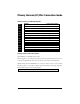
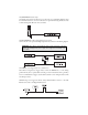
Primary Harness (H1) Wire Connection Guide Primary Harness (H1) Wiring Diagram H1/1 ___ ORANGE H1/2 ___ WHITE H1/3 ___ WHITE/BLUE H1/4 ___ BLACK/WHITE H1/5 ___ GREEN H1/6 ___ BLUE H1/7 ___ VIOLET (+) Door Trigger Input, Zone 3 H1/8 ___ BLACK (-) Chassis Ground Input H1/9 ___ OPEN H1/10 ___ BROWN H1/11 ___ RED H1/12 ___ RED/WHITE (-) 500 mA Armed Output (+)/(-) Selectable Light Flash Output (-) Remote Start Activation Input (-) 200 mA Domelight Supervision Output (-) Door Trigger In
H1/2 WHITE (+/-) Selectable Light Flash Output As shipped, this wire should be connected to the (+) parking light wire. If the light flash polarity jumper is moved to the (-) position (see the Programming Jumper section of this guide), this wire supplies a (-) 200 mA output. This is available for driving (-) light control wires in Toyota, Lexus, BMW, some Mitsubishi, some Mazda, and other models.
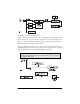
H1/3 WHITE/BLUE Activation Input A momentary input on this wire will start or stop the motor, just as transmitting Channel 3 from the transmitter/receiver does. It is often connected to an optional momentary push-button switch to make activating Valet Take Over more convenient. H1/4 BLACK/WHITE (-) 200 mA Domelight Supervision Output Connect this wire to the optional domelight supervision relay as shown in the following diagram: IMPORTANT! This output is only intended to drive a relay.
H1/6 BLUE (-) Multiplexed Trigger Input, Zone 1 and Trunk Icon This input will respond to a negative input with a WarnAway® or instant trigger. It is ideal for hood and trunk pins and will report on Zone 1. It can also be used with Directed dual-stage sensors. The H1/6 BLUE WarnAway® or instant trigger wire can also be used to shunt sensors during operation of auxiliary channels or remote start. (See Bypassing Sensor Inputs section of this guide.
H1/10 BROWN (+) Siren Output Connect this to the red wire of the siren. Connect the black wire of the siren to (-) chassis ground, preferably at the same point you connected the control module’s black ground wire. H1/11 RED (+)12V Constant Power Input Before connecting this wire, remove the supplied fuse. Connect to the battery positive terminal or the constant 12V supply to the ignition switch. NOTE: Always use a fuse within 12 inches of the point you obtain (+)12V.
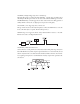
Secondary Harness (H2), Wire Connection Guide Secondary Harness (H2) Wiring Diagram H2/1 ___ GRAY/BLACK H2/2 ___ LIGHT GREEN/BLACK H2/3 ___ VIOLET/BLACK (-) Wait-to-Start Input (-) Factory Disarm/Special Accessory Output (-) Selectable Channel 4 Output Secondary Harness Wire Descriptions H2/1 GRAY/BLACK (-) Diesel Wait-to-Start Bulb Input Connect this wire to the wire in the vehicle that sends the signal to turn on the WAIT-TO-START bulb in the dashboard.
H2/2 LIGHT GREEN/BLACK (-) Factory Disarm Output This wire sends a negative pulse every time the remote start is activated or the alarm is disarmed. This can be used to pulse the disarm wire of the vehicle's factory anti-theft device. Use a relay to send a (-) or (+) pulse to the disarm wire as shown in the diagrams below. This wire can also be used as a special accessory output. (See Feature Descriptions section of this guide.
IMPORTANT! Never use this wire to drive anything but a relay or a low-current input! This transistorized output can only supply 200 mA, and connecting directly to a solenoid, motor, or other high-current device will cause the module to fail. Relay Satellite Ignition Switch Interface Wire Connection Guide Heavy Gauge Relay Satellite Wiring Diagram All except the red heavy gauge wires leading from the relay satellite are used to energize high current circuits in the vehicle.
ORANGE (+) Accessory Output Connect this wire to the accessory wire in the vehicle that powers the climate control system. PURPLE (+) Starter Output Connect this wire to the starter wire in the vehicle. NOTE: If failsafe starter kill is installed, be sure the PURPLE wire is connected to the car side of the failsafe starter kill relay. PINK/WHITE (+) Output to Second Ignition Circuit Connect this wire to the second ignition wire in the vehicle.
Remote Start Harness Wire Descriptions H3/1 BLUE Status Output This wire supplies a 200mA output as soon as the module begins the remote start process and is normally used to activate an immobilizer bypass module. The H3/1 BLUE wire can also be programmed to rearm a factory anti-theft system when the remote start shuts down. (See the Feature Descriptions section in this guide.) NOTE: This wire can also be used to bypass optional sensors and door triggers as described in the following diagram.
H3/3 GRAY (-) Hood Pinswitch Input, Zone 6 and Hood Icon This wire MUST be connected to hood pinswitch. This input will disable or shut down the remote start when the hood is opened. It will also trigger the security system if the hood is opened while the system is armed and report Zone 6. H3/4 BROWN (+) Brake Switch Input This wire MUST be connected to the vehicle's brake light wire. This is the wire that shows (+) 12V when the brake pedal is pressed.
IMPORTANT! Always perform the Vehicle Safety Check section of this guide to verify that the vehicle cannot be started in ANY drive gear and that the override switch is functioning properly. Neutral Safety Switch Interface Some vehicles combine the column shift mechanism and the mechanical neutral safety switch into one mechanical part. In these vehicles, it is impossible to interface the remote start system before the neutral safety switch.
Door Lock Harness (H4), Wire Connection Guide H2/A ___ Green (-) Lock, (+) Unlock Output H2/B ___ Empty Unless Using 451M H2/C ___ Blue (-) Unlock, (+) Lock Output IMPORTANT! The door lock outputs are low current and should not be attached directly to any high current device; they are only to be used to activate relays NOTE: For detailed instructions about connecting to the vehicle’s power door lock systems, refer to the Door Lock Wiring guide (DirectFax Document 1041), available only to authorize
Valet/Program Switch, 2-Pin BLUE Plug The Valet/Program button should be accessible from the driver’s seat. It plugs into the BLUE port on the side of the unit. Since the system features Valet® by using the transmitter/receiver, the button can be well hidden. Consider how the button will be used before choosing a mounting location. Check for rear clearance before drilling a 9/32-inch hole and mounting the button.
GREEN (-) Multiplex Input If installing an optional Directed dual-stage sensor, connect to the GREEN wire off the shock sensor harness. RED and BLACK: RED is (+)12V Constant, BLACK is (-) Ground Do not use these for anything besides the plug-in shock sensor. Mounting the Transceiver Two-way in-vehicle transceiver position should be discussed with the vehicle owner prior to installation, since the antenna may be visible to the vehicle’s operator.
Programming Jumpers Light Flash Jumper This jumper is used to determine the light flash output. In the (+) position, the on-board relay is enabled and the unit will output (+)12V on the WHITE wire, H1/2. In the (-) position, the onboard relay is disabled. The WHITE wire, H1/2, will supply a 200 mA (-) output suitable for driving factory parking light relays. NOTE: For parking light circuits that draw 10 amps or more, the jumper must be switched to a (-) light flash output.
System Features Learn Routine The System Features Learn Routine dictates how the unit operates. Due to the number of steps, they have been broken up into three menus. It is possible to access and change any of the feature settings using the Valet/Program switch. However, this process can be greatly simplified by using the 998T Bitwriter. Any of the settings can be changed and then assigned to a particular transmitter, up to four, a feature called Owner Recognition.
5. Program the Feature. While HOLDING the Valet/Program switch, you can toggle the feature on and off using the transmitter/receiver. Pressing the lock button will select the one chirp setting. Pressing the unlock button will select the two chirp setting. (See System Features Menus section of this guide.) NOTE: Some features have more than two settings. Pressing the lock button selects the one-chirp setting; pressing the unlock button will cycle through all possible two-chirp settings. 6.
➤ ➤ No activity for longer than 15 seconds. Press the Valet/Program switch too many times. System Features Menus Items in bold text have been programmed to the default setting at the factory. Menu #1 - Basic Features Feature Number One Chirp Setting Two-Chirp Setting 1-1 Active arming Passive arming 1-2 Chirps ON Chirps OFF 1-3 Ignition-controlled door locks Standard door locks 1-4 Active locking only Passive locking 1-5 Panic with ignition ON No panic with ignition on 1-6 0.
Menu #3 - Remote Start Features Feature Number One Chirp Setting Two-Chirp Setting 3-1 Engine checking ON Engine checking OFF 3-2 Engine checking TACH Engine checking VOLTAGE 3-3 Run time: 12 minutes Run time: 24 or 60 minutes 3-4 Parking lights flashing Parking lights constant 3-5 Crank time 0.6 seconds 0.8, 1.0, 1.2, 1.4, 1.6, 1.8, 2.0, 4.
NOTE: Remember, when passive arming is selected, the unit will chirp 20 seconds after the last door is closed. The system does not actually arm or lock the doors until 30 seconds after the door has been closed. 1-5 PANIC WITH IGNITION ON: This feature controls whether or not the panic mode is available with the ignition on. In some states, there are laws prohibiting a siren sounding in a moving vehicle. This feature makes the system compliant with these regulations.
Menu #2 - Advanced Features 2-1 SIREN OUTPUT CONSTANT/PULSED: The system can be programmed to output pulses instead of a continuous output when the system is triggered. This is useful to honk the factory horn in applications where a siren is undesirable. Remember that the unit is only capable of supplying 1 amp of current. A relay will be required to interface with most factory horn systems.
2-7 IGNITION CONTROLLED DOME LIGHT SUPERVISION ON/OFF: If turned on, the system will turn on the dome light for 60 seconds when the ignition is turned off. The optional dome light supervision feature must be installed as described in the Wire Connection Guide. 2-8 DOUBLE PULSE UNLOCK ON/OFF: Some vehicles require two pulses on a single wire to unlock the doors. When the double pulse unlock feature is turned on, the BLUE H4/C wire will supply two negative pulses instead of a single pulse.
3-5 CRANK TIME 0.6/0.8/1.0/1.2/1.4/1.6/1.8/2.0/4.0 SECONDS: If the unit is programmed for no engine checking or voltage sense, the crank time must be set to the appropriate duration. The default setting is 0.6 second. If a different crank time is desired, select feature 3-5 and select either 0.6 second by using the one-chirp setting or toggle through the higher settings by using the twochirp settings. 3-6 VOLTAGE CHECK HI/LOW: This feature only functions when programmed for voltage sense.
2. Key. Turn the ignition ON. (The heavy-gauge PINK wire of the relay satellite must be connected.) 3. Select the receiver Channel. Press and release the Valet/program switch the number of times necessary to access the desired channel. Once you have selected a channel, press and HOLD the Valet/program switch once more. The siren will chirp and the LED will blink the number of times corresponding to the channel that has been accessed.
Channel #10: If any button from a known transmitter is programmed to Channel 10, all transmitters will be erased from memory and the system features will revert to the default settings. This is useful in cases where the one of the customer's transmitters is lost or stolen. This will erase any lost or stolen transmitters from the system's memory. It can also be used to start from scratch if the transmitter buttons were programmed incorrectly.
and operate Remote Start and operate Channel 4 The standard configuration also allows the user to utilize Multi-Level Security Arming, a feature that cannot be accessed from a single button arm/disarm configuration transmitter.
NOTE: A dim or pulsing LED when learning tach means the unit has not learned the tach signal. Test all connections, and if good, relocate the tach input wire and continue with tach learning procedure. Shutdown Diagnostics The unit has the ability to report the cause of the last shutdown of the remote start system. To enter diagnostic mode: 1. Turn the ignition off. 2. Press and hold the Valet/program switch. 3. Turn the ignition on then off again. 4. Release the Valet/program switch. 5.
LED FLASHES SHUTDOWN MODE 1 System timed out 2 Over-rev shutdown 3 Low or no RPM 4 Transmitter Shutdown (or optional push-button) 6 (-) Hood Shutdown (H3/3 GRAY) or (+) Brake Shutdown (H3/4 BROWN) 7 (-) Neutral safety shutdown (H3/6 BLACK/WHITE) 8 Wait-to-start timed out Multi-Level Security Arming Multi-Level Security arming allows the operator to select which inputs and sensors are active during a particular arming cycle.
Timer Mode Timer Mode allows the operator to program the remote start system to start the engine every three hours a total of 6 times. For a full description of Timer Mode activation refer to the owner's manual. Diagnostics The system’s microprocessor monitors and reports all active and violated zones when arming and disarming. LED flashes indicate the active or violated zone; siren chirps indicate system status.
Long-Term Event History The system stores the last two full triggers in memory. These are not erasable. Each time the unit sees a full trigger, the older of the two triggers in memory will be replaced by the new trigger. To access long term event history: 1. With the ignition off, press and HOLD the Valet/Program switch. 2. Turn on the ignition. 3. Release the Valet/Program switch. 4. Press and release the Valet/Program switch within 5 seconds.
Safety Check Before vehicle reassembly, the remote system must be checked to ensure safe and trouble-free operation. The following test procedure must be used to verify proper installation and operation of the system. The installation must be completed before testing, including connection to the brake switch and hood switch. 1. Test the BRAKE shutdown circuit: With the vehicle in Park (P), activate the remote start system. Once the engine is running, press the brake pedal.
Troubleshooting Alarm Troubleshooting Starter kill doesn't work: ➤ Is the correct wire being interrupted? If the car starts when the starter kill relay is completely disconnected, the wrong starter wire has been cut and interrupted. ➤ Is the yellow wire of the starter kill relay going to primary ignition? This wire must be powered in the run and start positions. Shock sensor doesn't trigger the alarm: ➤ Has the NPC™ system been triggered? If so, you will hear 5 chirps when disarming.
The Valet®/Program switch doesn't work. ➤ Is it plugged into the correct socket? See Plug-In LED and Valet®/Program Switch section of this guide. Status LED doesn't work. ➤ You've probably guessed already, but here goes: Is it plugged in? (See Plug-In LED and Valet®/Program Switch section of this guide.) Is the LED plugged into the correct socket? Door locks operate backwards. ➤ This unit has easily-reversed lock/unlock outputs. Recheck wire connections to see if you have reversed these.
The vehicle starts, but immediately dies. ➤ Does the vehicle have an immobilizer? The vehicle’s immobilizer will cut the fuel and/or spark during unauthorized starting attempts. ➤ Is the remote start programmed for voltage sense? If so, the start time may not be set high enough, or you may have to adjust the voltage threshold in programming. Voltage sense will not work on some vehicles. ➤ Check diagnostics. Sometimes a shutdown will become active during cranking or just after cranking.
© 2003 Directed Electronics, Inc.
Wiring Quick Reference Guide © 2003 Directed Electronics, Inc.
© 2002 Directed Electronics, Inc.