MOD E R460 L
Limited lifetime consumer warranty Directed Electronics ("Directed") promises to the original purchaser to repair or replace with a comparable reconditioned model any Directed unit (hereafter the "unit"), excluding without limitation the siren, the remote transmitters, the associated sensors and accessories, which proves to be defective in workmanship or material under reasonable use during the lifetime of the vehicle provided the following conditions are met: the unit was professionally installed and servi
CONSEQUENTIAL DAMAGES OF ANY KIND. IN THE EVENT OF A CLAIM OR A DISPUTE INVOLVING DIRECTED OR ITS SUBSIDIARY, THE PROPER VENUE SHALL BE SAN DIEGO COUNTY IN THE STATE OF CALIFORNIA. CALIFORNIA STATE LAWS AND APPLICABLE FEDERAL LAWS SHALL APPLY AND GOVERN THE DISPUTE. THE MAXIMUM RECOVERY UNDER ANY CLAIM AGAINST DIRECTED SHALL BE STRICTLY LIMITED TO THE AUTHORIZED DIRECTED DEALER'S PURCHASE PRICE OF THE UNIT.
Table of contents Limited lifetime consumer warranty . . . . . . . . . . . . . . . . . . . . . . . . . . . . . . . . . . . . . . . i 2-way LCD remote control . . . . . . . . . . . . . . . . . . . . . . . . . . . . . . . . . . . . . . . . . . . . . 1 LCD screen . . . . . . . . . . . . . . . . . . . . . . . . . . . . . . . . . . . . . . . . . . . . . . . . . . . . . . . . . 2 Standard remote configuration . . . . . . . . . . . . . . . . . . . . . . . . . . . . . . . . . . . . . . . . . . 3 What is included .
Owner recognition. . . . . . . . . . . . . . . . . . . . . . . . . . . . . . . . . . . . . . . . . . . . . . . . . . . 31 Rapid resume logic . . . . . . . . . . . . . . . . . . . . . . . . . . . . . . . . . . . . . . . . . . . . . . . . . . 32 Power saver mode . . . . . . . . . . . . . . . . . . . . . . . . . . . . . . . . . . . . . . . . . . . . . . . . . . . 32 Programming . . . . . . . . . . . . . . . . . . . . . . . . . . . . . . . . . . . . . . . . . . . . . . . . . . . . . . .
2-way LCD remote control 6 3 1 5 1. Auxiliary Channel Button 2. Arm Button 3. LCD Screen (see LCD Screen) 4. Disarm Button 5. Panic Button 6. Battery Compartment 7.
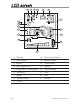
LCD screen 1 2 3 4 5 6 7 17 16 15 14 8 13 9 12 10 11 1. Transmit 10. Battery level indicator 2. Out of range 11. Remote sending 3. Receive 12. Vibrate mode 4. Aux Output 2 or 3 13. Ignition 5. Garage door (519H2 option) 14. Vehicle number 6. Warn Away® 15. Door 7. Alarm 16. Arm 8. Trunk or Hood 17. Disarm 9.
Standard remote configuration controls the Lock–Arm/Panic On/Panic Off function. controls the Unlock–Disarm/Panic Off function. controls Silent Mode™ and an Auxiliary Output (2). or controls the Panicc On/Off function (hold for 2- seconds). and P pressed together control an Auxiliary Output (3). (located on back of the remote) selects the vehicle to control and also provides user selection of LCD remote response .
What is included ➤ Control module ➤ 1 four-button 2-way LCD transmitter 1 four-button transmitter ➤ note: On both remotes the panic button is the same color.
➜ System maintenance This system needs no specific maintenance beyond remote control battery replacement. The 2-way remote is powered by a 1.5V AAA battery. The 1-way remote is powered by a pair of 3V, CR2016 batteries. Battery Level Indicator (2-way remote) The Battery Level indicator has four level indicators that serve as a visual indication of battery charge.
keep your proof of purchase, which reflects that the product was installed by an authorized dealer. Make sure that you receive the warranty registration from your dealer. ➜ FCC/ID notice This device complies with Part 15 of FCC rules. Operation is subject to the following two conditions: (1) This device may not cause harmful interference, and (2) This device must accept any interference received, including interference that may cause undesirable operation.
Replacement remote controls You can purchase replacement remote controls from your Authorized Dealer or on-line at the following web site: www.directedstore.com Once you receive your new remote control, please refer to instructions included on the remote packaging. 2-way LCD remote control functions The LCD remote control buttons are used to send commands to the system. The descriptions below reflect the standard configuration for this system.
Button Silent Mode™ and an optional auxiliary function are controlled by pressing this button. (Silent Mode™ works by pressing this button for less than one second before arming or disarming. An optional auxiliary function, such as trunk release, can be controlled by pressing this button for 1.5 seconds.) The auxiliary output controls __________________________. or Button The panic feature is controlled by pressing this button for approximately two seconds.
➜ Standard LCD icon configurations (2-way only) Icon The transmit icon will be displayed while the remote control is transmitting a command to the vehicle. Icon The signal icon will be displayed if a command is transmitted to the vehicle but the command page is not received. Icon The receive icon will be displayed while the remote control is receiving a page from the vehicle.
Icon The trunk icon will display for full alarm by flashing for a few seconds and then display continuously until the page is cleared. Icon The shock sensor icon will display for both Warn Away® and full alarm by flashing for a few seconds and then display continuously until the page is cleared. Icon The battery icon always displays the current charge capacity remaining in the remote’s battery.
press and release the program button until the vehicle number is shown. For example, If the remote was originally on vehicle number 1 and a trigger page was received for vehicle number 2, the remote will show the trigger alarm and show number 2 on the display. After clearing the page, press and release the program button until number 1 is displayed. Now you can operate the alarm system on vehicle number 1.
Transmitter functions This system uses a computer-based learn routine to learn the transmitter buttons. This makes it possible to assign any transmitter button to any system function. The transmitter initially comes programmed with Standard Configuration, but may also be customized by an authorized dealer. The buttons described in this manual correspond to a Standard Configuration transmitter.
Alarm Page If the alarm system is triggered while armed, an Alarm Page will be sent to the remote control. When the remote receives an Alarm Page, the LCD icons will display the alarm system status information and the remote control will generate beeps and-or vibration. An Alarm Page alert is a series of 5 groups of 4 rapid beeps (shock, trunk, door, ignition, or hood trigger) and the LCD icon that caused the alarm will display.
Programming LCD remote ➜ To enter programming mode Press and hold the P button until one long beep is heard. Programming mode to customize the remote’s response is now entered. note: If no buttons are pressed within 5-seconds, programming mode will exit with 2-beeps. ➜ Beeps/Vibration On/Off Press to select beeps/vibration On/Off. Beeps alone, vibra- tion alone, beeps and vibration, or no beeps and vibration can be selected. Refer to the table below for these settings.
➜ Illumination On/Off Press to select LCD backlight illumination On/Off. The LCD backlight will illuminate when a remote button is pressed, or an alarm status page is received. LCD Backlight settings Programming response ON 1-beep, backlight ON OFF 2-beeps, backlight OFF ➜ Page notification The remote control can be programmed to notify the user of a page (audibly beeping if the vehicle’s status changes, e.g. door unlocked, engine started, vehicle violation, etc.).
Using your system The buttons described in this manual correspond to the standard configuration. Remember, this is not the only way your transmitter may be set up. It can be custom configured to meet your needs. See your installer for additional details. ➜ Active arming You can arm the system by pressing of your remote for one second. When the system arms, from the vehicle you will hear a short siren sound, or chirp, and see the parking lights flash once.
Passive arming The system can be programmed to arm itself automatically (called passive arming). If the system is programmed for passive arming, it will automatically arm 30 seconds after the ignition is turned off and the system detects that you have left the vehicle by opening and closing a door. Whenever the system is in its 30-second passive arming countdown, the in-vehicle status LED will flash twice as fast as it does when the system is armed.
➤ ➤ ➤ chirping the siren and flashing the parking lights. Three seconds later, the siren output changes to a continuous blast. This progressive response gives you time to disarm the system with your LCD remote if you inadvertently open the door while the system is armed, while still providing instant response (even if the door is immediately closed). Turning on the ignition key will trip the same progressive response as opening a door. The optional starter kill prevents the vehicle’s starter from cranking.
➤ Press a third time witihin 5 seconds, the siren chirps 3 times then followed by a long chirp. Zone 4 is now bypassed. ➤ Press a fourth time within five seconds: The siren cirps four times follwed by a long chirp. Zone 2 and 4 are now bypassed. ➤ Press a fifth time within five seconds: The siren chirps five times followed by a long chirp. All input zones, except the ignition are now bypassed. ➤ Hold down the to begin the Multi-Level-Security Arming cycle over again.
The remote will indicate disarm notification with 2 beeps and 5 flashes of the icon. If disarming after the system has been triggered, the remote control will send a diagnostic notification as a reminder. These diagnostic notifications are: 1. If a sensor triggered the system, the remote will emit 4 quick beeps and the LCD screen will indicate which sensor (5flashes) tripped the alarm. 2.
➜ Disarming without a transmitter This feature allows you to disarm the security system without the remote transmitter should it be lost, damaged, or disabled. In order to disarm the system without a remote transmitter, you must have the vehicle’s ignition key and know where the Valet button is located. Be sure to check with the installer for the location and the number of presses of the Valet button required to disarm the system. To disarm the security system, turn the ignition to the ON position.
➜ Dome light control (optional) security only The dome light activates for 30 seconds after the system is disarmed. Ignition controlled The dome light activates for 30 seconds after the ignition is turned Off. door controlled The dome light activates for 30 seconds after the system sees a door has closed. (If door was held open for longer than 3 minutes the dome light will not illuminate.) full The dome light activates for 30 seconds after seeing door closure, ignition, or security disarm.
The LCD remote responds with the normal arm/disarm notifications in silent mode. (If the remote has beeps programmed On, the remote will beep.) ➜ Panic mode note: On both remotes the panic button is the same color. LCD remote If you are threatened in or near your vehicle, you can attract attention by triggering the system with your LCD remote. Just press or button for approximately two seconds, and you will enter Panic Mode.
➜ Valet mode You can prevent your security system from automatically arming and triggering by using Valet Mode. This is very useful when washing the vehicle or having it serviced. In Valet Mode, the security system will not arm, even with the remote transmitter, but all convenience functions (door locks, trunk release, etc.) will continue to work normally. To enter or exit Valet Mode: 1. Turn the ignition on. 2. Turn the ignition off. 3. Press and release the Valet DRW-35 button within 10 seconds.
➜ Nuisance prevention® circuitry Your system has Directed’s Nuisance Prevention® Circuitry (NPC®). It prevents annoying repetitive trigger sequences due to faulty door pin switches or environmental conditions such as thunder, jackhammers, airport noise, etc. Example If the alarm triggers three times within a 60-minute period and each time the same sensor or switch triggers the alarm, NPC® will interpret those triggers as false alarms.
Auxiliary outputs (options) This system also supplies outputs that can control convenience options such as remote control trunk release and window automation. Consult your dealer for available options for your system. Channel 2 Trunk release: When connected, pressing for 1.5 seconds will remotely release the vehicle trunk lid. Channel 3 auxiliary output: When connected, pressing and will immediately activate this output to control an additional convenience option.
Diagnostics The microprocessor at the heart of your security system is constantly monitoring all of the switches and sensors that are connected to it. It detects any faulty switches and sensors and prevents them from disabling the entire system. The microprocessor will also record and report any triggers that occurred during your absence. Refer to the System Status Chirps and Table of Zones charts for diagnostic information.
➜ Disarming diagnostics Extra disarm chirps are the Tamper Alert. If four chirps are heard when disarming, the system was triggered in your absence. If five chirps are heard, a zone was triggered so many times that Nuisance Prevention® Circuitry has bypassed that zone (see NPC section of this guide). The in-vehicle status LED will indicate which zone was involved. (See Table of Zones section of this guide.
➜ Table of zones The zone number is the number of LED flashes used by the system to identify that input. The standard input assignments are listed below, along with spaces to write in any optional sensors or switches you have had installed. Zone - Number of LED Flashes Description 1 Instant trigger - often used for trunk pinswitches 2 Shock sensor input - a light impact activates warn away and a heavier impact activates full alarm.
➜ Interpreting zone diagnostics Warn Away responses are not reported by arming or disarming diagnostics. If you receive a Bypass notification when arming or a Tamper Alert notification when disarming, look at the invehicle status LED. Active or triggered zones will be indicated by a pattern of blinks by this LED. Example If Zone 3 was active or triggered, the in-vehicle LED will blink three times with a two-second pause. Then it will blink three times again, and repeat until the ignition is turned on.
the transmitter several times within range of the vehicle. The alarm will automatically re-sync and respond to the transmitters normally. Owner recognition Owner Recognition is a feature available exclusively from Directed. Using the Directed Bitwriter®, a hand-held programming tool, your dealer can program many of the system settings. The programmer makes it possible to program different settings for each transmitter that is used with the system.
Rapid resume logic This Directed system will store its current state to non-volatile memory. If power is lost and then reconnected, the system will recall the stored state from memory. This means if the unit is in Valet Mode and the battery is disconnected for any reason, such as servicing the car, when the battery is reconnected the unit will still be in Valet Mode. This applies to all states of the system including arm, disarm, VRS®, and Valet Mode.
Programming Programming options control what your system does during normal operation, and require few or no additional parts. However, some may require additional installation labor. The following is a list of the program settings, with the factory settings in Bold: ➤ ➤ ➤ ➤ Active arming (only with the remote) or passive arming (automatic arming 30-seconds after the last door has been closed). Arming/disarming confirmation siren chirps on or off.
note: When programmed for passive arming and active lock, if the system is disarmed without a door being opened, the system will relock the doors when it passively rearms. ➤ Panic mode enabled/disabled with the ignition on: Some states have laws against siren capability in a moving vehicle.
feature by turning the ignition key to the RUN position and pressing the Valet® button the programmed number of times. AED is disabled when the system is in Valet® Mode. note: This feature will only function if the Failsafe® Starter Kill relay has been installed. ➤ Full trigger response 30 or 60 seconds: This determines how long the full triggered sequence lasts. Some states have laws regulating how long a security system can sound before it is considered a nuisance.
➤ Progressive door trigger on or off: When the system is armed and a door is opened, the system responds with ten chirps prior to beginning the full triggered sequence. If an instant trigger is desired, the progressive door trigger can be programmed off. ➤ Valet® pulse count: The number of presses of the Valet® button required to disarm the security system, AED, or the VRS® system can be programmed from one to five presses. The default setting is one press.
Installation options The system has many options that may require extra parts and labor. Some of the possibilities are listed here. ➤ Progressive unlocking: In most cars with electric power door locks, the system can be configured so that when the system is disarmed, only the driver’s door unlocks. A second press of the button unlocks the other doors. ➤ Vehicle Recovery System (VRS®): VRS is an anti-carjacking device designed to help in the safe recovery of your vehicle in case of a carjacking.
Directed has engineered this vehicle security system, the Failsafe® Starter Kill, and the VRS feature to provide the best combination of personal safety and property protection available. When properly installed, the system can never inadvertently stop your vehicle in traffic or on railroad tracks while the vehicle is in operation. It is unlike other systems that shut down your engine while it is running. This system is designed to perform starter interrupt, or starter kill.
if someone takes your keys and remote transmitter by force in a parking lot. note: If the VRS® system is armed while operating the vehicle and not disarmed prior to leaving the vehicle, it is still armed and will trigger the next time the vehicle is driven. ➜ Triggered sequence, VRS Fifteen seconds after the last door has closed, the in-vehicle LED will begin flashing. This delay is intended to allow you time to distance yourself from your vehicle in the event of a carjacking.
➜ Disarming the VRS Take the time to familiarize yourself with the VRS triggering sequence and the disarm procedure. It is important to recognize and identify the VRS trigger sequence and know how to disarm it in case of accidental activation. Once the VRS is armed, it does not disarm automatically. You must disarm it the next time you operate the vehicle. You must disarm it with one of the following procedures: If the system has not entered the triggered sequence (siren has not started chirping): 1.
Security & convenience expansions Here we have listed only some of the many expansion options available. Please contact your dealer for a complete explanation of all the options available to you. Audio Sensor: Metal on glass, glass cracking, and breaking glass each produce distinctive acoustic signatures. The 506T audio sensor uses a microphone to pick up sounds, and then analyzes them with proprietary acoustic software to determine if the glass has been struck.
can also be used to turn on your parking and headlights for a programmed time. Power Trunk Release: The channel two output of the system can operate a factory power release for the vehicle’s trunk or hatch. (An additional relay may be required.) If the factory release is not power activated, then Directed's 522T trunk release solenoid can often be added. Power Window Control: Automatic power window control is pro- vided with the 529T and 530T systems.
Glossary of terms ASK Amplitude Shift Keying—a method of transmitting data. Control Unit: The "brain" of your system. Usually hidden under the dash area of the vehicle. It houses the microprocessor which monitors your vehicle and controls all of the system's functions. Fail Safe Starter Kill: An automatic switch controlled by the secu- rity system which prevents the vehicle’s starter from cranking whenever the system is armed.
"chirps" you hear, as well as the six tones you hear while the alarm is triggered. Transmitter: Hand-held, remote control which operates the various functions of your system. Trigger or Triggered Sequence: This is what happens when the alarm "goes off" or "trips". The triggered response of your system consists of the siren sounding and parking light flashing for the programmed duration. Valet Button: A small push-button switch mounted somewhere inside the vehicle.
✂ QUICK REFERENCE GUIDE To arm using your LCD remote Cut along dotted line and fold for a quick and easy reference to keep in your purse or wallet. ➤ You can activate, or arm, the system by pressing on your remote for one second. When the system arms, you will hear a short siren sound, or chirp, and the parking lights will flash once. If the vehicle’s power door locks have been connected to the system, the doors will lock. To disarm using your LCD remote ➤ To disarm the system, press .
The company behind Python® Auto Security Systems ELECTRONICS Vista, CA 92081 www.directed.com is Directed Electronics. Since its inception, Directed Electronics has had one purpose, to provide consumers with the finest vehicle security and car stereo products and accessories available. The recipient of nearly 100 patents and Innovations Awards in the field of advanced electronic technology, Directed Electronics is ISO 9001 registered.
- I ® Responder 460 Installation Guide NOTE: This product is intended for installation by a professional installer only! Any attempt to install this product by any person other than a trained professional may result in severe damage to a vehicle's electrical system and components. E L E ( T RON I ( S ©2008 Directed Electronics, Vista, Ca.
The Bitwriter® (pin 998T) requires chip version 2.4 or newer to program this unit. Bitwriter™, Code Hopping™, DEI®, Doubleguard®, ESPTM, FailSafe®, Ghost Switch™, Learn Routine™, Nite-Lite®, Nuisance Prevention® Circuitry, NPC®, Revenger®, Silent Mode™, Soft Chirp®, Stinger®, Valet®, Vehicle Recovery System®, VRS®, and Warn Away® are all Trademarks or Registered Trademarks of Directed Electronics, Inc.
Contents Primary Harness (H 1) Wire Connection Guide Primary Harness Wiring Diagram Primary Harness Wiring Instructions Door Lock Harness (H2), 3-PIN Connector Plug-In LED and valet/program switch Programmer Interface, 3-Pin BLACK Plug Mounting the Antenna Receiver On-Board Dual-Stage Shock Sensor Optional Sensor Harness, 4-pin Connector Programming Jumper Light Flash Jumper Bypassing Sensor Inputs System Features Learn Routine System Features Menus Menu #1 - Basic Features Menu #2 - Advanced Features Featu
Primary Harness (H1) Wire Connection Guide Primary Harness Wiring Diagram (-) 500 rnA Armed Output I (+)1(-) Selectable Light Flash Output I IORANGE IWHITE (-) Door Trigger Input, Zone 3 I I I (-) Instant Trigger Input, Zone 1 I IVIOLET (+) Door Trigger Input, Zone 3 I IBLACK (-) Chassis Ground Input I (+) Switched Ignition Input, Zone 5 I (+) Siren Output I IWHITE/BLUE IBLACKIWHITE (-) 200 rnA Channel 3 Programmable Output (-) 200 rnA Domelight Supervision Output IGREEN IBLUE IYELLOW
IMPORTANT! Never interrupt any wireofher thafl the starter wire.' PRE-WIRED STARTER Kill RELAY TO OPTIONAL SENSORS, 529T, 530T, ETC, TO STARTER MOTOR Hl/2 WHITE (+1-) light flash output As shipped, the HI 12 WHITE wire should be connected to the (+) parking light wire. If the light flash polarity jumper is moved to the (-) position (see the Programming Jumper section of this installation guide), this wire supplies a (-) 200 rnA output.
PARKING LIGHT BULB WHITE H1/2 (+) LIGHT FLASH OUTPUT ~~~~---~~~~C==-=H ....l....- (+) 12V I PARKING LIGHT RELAY OR SWITCH DIA-l WHITE H1/2 (-) LIGHT FLASH OUTPUT FACTORY PARKING LIGHT RELAY PARKING LIGHT SWITCH Hl/3 WHITE/BLUE 200 rnA (-) channel 3 output This wire provides a (-) 200 rnA output whenever the transmitter button(s) controlling channel three is pressed.
IMPORTANT! Never use this wire to drive anything but a relay or a low-current input! This transistorized output can only supply 200 mA, and connecting directly to a solenoid, motor, or other high-current device will cause the module to fail. Hl/4 BLACK/WHITE (-) 200 rnA domelight supervision output Connect the HI /4 wire to the optional domelight supervision relay as shown in the following diagram: IMPORTANTl This output is only intended to drive a relay.
DOMELIGHT ~ M~) I (-j DOOR SWITCH _ (\ 0-l-----------'------ -'1 DfA_2741r---(+-)1-2-V Hl/6 BLUE (-) instant trigger input This input will respond to a negative input with an instant trigger. It is ideal for hood and trunk pins and will report on Zone 1. It can also be used with Directed single-stage sensors. The Hl/6 blue instant trigger wire can also be used to shunt sensors during operation of auxiliary channels or remote start. (See Bypassing Sensor Inputs section of this guide.
grounded at the same location. \ GROUND WIRE OIA..a.4 NOTE: REMOVE ANY PAINT BELOW RING CONNECTOR RING CONNECTOR Hl/9 YELLOW (+) ignition input Connect this wire to the (+) 12 volts ignition wire. This wire is pre-wired to the starter kill relay and must show (+) 12 volts with the key in RUN position and during cranking. Take great care that this wire cannot be shorted to the chassis at any point.
HI/II RED (+)12V constant power input Before connecting this wire, remove the supplied fuse. Connect to the battery positive terminal or the constant 12V supply to the ignition switch. NOTE: Always use a fuse within 12 inches of the point you obtain (+)12V. Do not use the 15 amp fuse in the harness for this purpose. This fuse protects the module itself. HU12 RED/WHITE 200 rnA (-) channel 2 output When the system receives the code controlling channel 2 for longer than 1.
Door Lock Harness (H2), 3-PIN Connector IGreen IEmpty IBlue (-) Lock, (+) Unlock Output I Unless Using 451 M I (-) Unlock, (+) Lock Output I IMPORTANTI The door lock outputs· are .low current and should not be attached directly to any high current device; they are only to be used to activate relays. For detailed instructions about connecting to the vehicle's power door lock systems, refer to the Door Lock Wiring guide (Document No.
Peripheral Plug-in Harness Super Bright LED, 2-Pin WHITE Plug The super bright LED operates at (+) 2 volt DC and plugs into the two-pin WHITE port. Make sure the LED wires are not shorted to ground as the LED will be damaged. Multiple LED's can be used, but they must be wired in series. The LED fits into a 9/32-inch mounting hole. Be sure to check for clearance prior to drilling the mounting hole. NOTE: Never use a BLUE LED in combination with a RED LED.
Valet/Program Switch, 2-Pin BLUE Plug The Valet/Program button should be accessible from the driver's seat. It plugs into the BLUE port on the side of the unit. Since the system features Valet® by using the remote transmitter, the button can be well hidden. Consider how the button will be used before choosing a mounting location. Check for rear clearance before drilling a 9/32-inch hole and mounting the button.
Mounting the Antenna/Receiver The antenna/receiver's position should be discussed with the vehicle owner prior to installation, since it will be visible to to the vehicle's operator. The best location for the Antenna/receiver is centered high on either the front or rear windshield. For optimal range, the antenna should be mounted vertically. It can be mounted horizontally in relation to the windshield or under the dashboard away from metal, but range will be diminished.
Imj:J~irlt • . r~.~~.i~ye(#l~;,.~$t~$l~I~>5r~~fr~.~~r;t~~ve·.t~~· ant~tl~f·~~'.;'~f1;/~~Adt~u,,~r.··tf:1e><~~~';'<.4._,~;~~end.t he cabl~fUU··tEJ,flgth;dltdnQ;jl'l$t8J1ation;; l0c4tiOrl.·'// ',." ,..'. . " ' . , ......' rega(~I$$$~()ftheanten"aDlOunting ' . ........" .' '.'" ' ' ..' Antenna receiver cable On-Board Dual-Stage Shock Sensor Less Sensitive More Sensitive DRW·52 There is a dual-stage shock sensor inside the control unit.
Optional Sensor Harness, 4-pinConnector The four-pin sensor harness is optional, and is not included with this unit. RED (+) 12V Constant and BLACK (-) Ground These wires supply constant (+) 12 volts and ground to the optional sensor. BLUE/GREEN (-) Multiplex Input These wires are multiplex inputs. If a (-) input of less than 0.8 seconds is supplied to either wire, the Warn-Away response will occur. A (-) input of longer than 0.
NOTE: For parking light circuits that draw 10 amps or more, the jumper must be switched to a (-) light flash output. PIN 8617 or a standard automotive SPDT relay must be used on the H 1/2 light flash output harness wire. .. Important! DO. NOT connect .' the H112 ,Hghtflashwire to a.. . ne~~ti'/e . . . yehiclelight··.·fla$h•.·.··wirEl•.• ··bef~r~ .changing.• the progrS11'lrning jumper to.theneg~tivepol~ritypos·itionor damage to vehicle light circuit may occur. .
System Features Learn Routine The System Features Learn Routine dictates how the unit operates. Due to the number of steps, they have been broken up into two menus. It is possible to access and change any of the feature settings using the Valet/Program switch. However, this process can be greatly simplified by using the 998T Bitwriter. Any of the settings can be changed and then assigned to a particular transmitter, up to four, a feature called Owner Recognition.
4. Select a Feature. Press and release the Valet/Program switch the number of times corresponding to the feature you wish to change. For example, to access the third feature, press and release the switch three times. Then press the switch once more and HOLD it. The siren will chirp the number of times equal to the step you have accessed. 1I1~~0~ \. ' v. \ DRW·35 / '~ I ! I Jj 5. Program the Feature.
To access another feature in the same menu: • • Press and release the Valet/Program switch the number of times necessary to advance from the feature you just programmed to the next one you want to program. Then press the Valet/Program switch once more and HOLD it. For example, if you just programmed the third feature in the menu and you would like to program the seventh feature in the menu, you would press and release the Valet/Program switch four times and then press it once more and hold it.
System Features Menus Menu #1 - Basic Features Items in bold text have been programmed to the default setting at the factory. One Chirp Setting Two-Chirp Setting 1-1 Active arming Passive arming 1-2 Chirps ON Chirps OFF 1-3 Ignition controlled door locks ON Ignition controlled door locks OFF 1-4 Active locking only Passive locking 1-5 Panic with ignition on No panic with ignition on 1-6 0.8 second door lock pulses 3.
Menu #2 - Advanced Features One Chirp Setting Two-Chirp Setting 2-1 Siren Horn honk 2-2 3O-second siren duration 60-second siren duration* 2-3 Nuisance Prevention- Circuitry ON Nuisance Prevention- Circuitry OFF 2-4 Progressive door trigger Instant door trigger 2-5 Valet switch Input: 1 pulse Valet switch input: 2-5 pulses 2-6 Bypass Notification ON Bypass Notification OFF 2-7 Ignition-controlled domelight ON Ignition-controlled domelight OFF 2-8 Single unlock pulse Double unlock pu
·.. 1-3 IGNITION CONTROLLED DOOR LOCKS ON/OFF: • When turned on, the doors will lock three seconds after the ignition is turned on and unlock when the ignition is turned off. The 998T Bitwriter will display separate steps for ignition lock and ignition unlock. They can be programmed on or off independently.
1-8 AUTOMATIC ENGINE DISABLE (AED) ON/OFF: AED is a full-time, passive starter disable that works independently of the security system. When turned on, the orange, ground-when-armed output (H 1/1) will go active 30 seconds after the ignition is turned off. The LED will flash at half its normal rate when the ignition is turned off to indicate that AED is active and will interrupt the starter in 30 seconds. AED does not occur in Valet mode and can be bypassed using the emergency override procedure.
2-3 NUISANCE PREVENTION® CIRCUITRY (NPC®) ON/ OFF: NPC® stops repeated triggering of the same zone. If one zone is triggered three times in one hour, that zone is bypassed for one hour, starting from the time of the third trigger. During that hour, if the system detects a trigger on that zone again, the system resets the one hour timer. If one hour passes and the zone has not triggered again, the zone is activated and can trigger the system again.
2-8 DOUBLE PULSE UNLOCK ON/OFF: Some vehicles require two pulses on a single wire to unlock the doors. When the double pulse unlock feature is turned on, the BLUE H2/C wire will supply two negative pulses instead of a single pulse. At the same time, the GREEN H2/A wire will supply two positive pulses instead of a single pulse. This makes it possible to directly interface with double pulse vehicles without any extra parts.
Transmitter/Receiver Learn Routine The system comes with two transmitters that have been taught to it. The system can store up to four different transmitter codes in memory. Use the following learn routine to add transmitters to the system or to change button assignments if desired. If the system was previously programmed using the 998T Bitwriter, the learn routine may be locked.
Channel Number 1 2 3 Function Arm/Disarm Panic only Silent Mode/Remote ValetlTrunk Release Remote Start or other accessories Arm only Disarm only Auto-learn standard configuration* (four-button transmitter) Auto-learn three-button configuration* Delete all transmitters 4 5 6 7 8 9 Wire Color RED/WHITE WHITE/BLUE *NOTE: For Auto Learn Configurations, see Transmitter Configurations section of this guide. IIi~i:~'1 ~x) / ..' ~ 4.
~ 5. Release. Once the code is learned, the Valet/Program button can be released. To exit the learn routine: One long chirp indicates that Learn Routine has been exited. Learn Routine will be exited if any of the following occurs: • • • • 29 Ignition is turned off. Door is dosed. Valet/Program button is pressed too many times. More than 15 seconds elapse between steps. © 2008 Directed Electronics- All rights reserved.
Transmitter Configurations The transmitters can be programmed with the standard or three-button configurations by using the Auto Learn functions in the TransmitteriReceiver Learn Routine. Standard Configuration When programmed for standard configuration, the transmitter buttons are assigned to th~Jollowing functions: ' ''. .',.·8.· ,.,:- ", I '."i operates Arm only operates Disarm only operates Channel 2 and Silent Mode 'Af ...n'. '.
Diagnostics The system's microprocessor monitors and reports all active and violated zones when arming and disarming. LED flashes indicate the active or violated zone; siren chirps indicate system status. Arm/Disarm Diagnostics The number of siren chirps will indicate the status of the alarm when arming and disarming. For information on which zone is active or has been violated refer to the Table of Zones.
Table of Zones Zone No. Trigger type Input description 1 Instant H1/6 BLUE - Connect to optional hood/trunk pins. 2 On-board shock sensor Heavy impact detected by the on-board shock sensor. 3 Two-stage, progresses from Door switch circuit. H1/5 GREEN or H1/7 VIOLET warning to full alarm 4 Multiplexed Input BLUE and GREEN wires of optional sensor plug. Inputs shorter than 0.8 seconds will trigger a Warn Away response, while inputs longerthan 0.
4. Press and release the Valet/Program switch within 5 seconds. The LED will flash in groups indicating the last two zones that triggered the unit. The LED will flash for one minute or until the ignition is turned off. NOTE: The Warning Zone triggers are not stored to memory and will not be reponed. Multi-Level Security Arming Multi-Level Security arming allows the operator to select which inputs and sensors are active during a particular arming cycle.
Optional Vehicle Recovery System (VRS) VRS is an optional feature designed to disable a vehicle during a carjacking event. It must be programmed in the features menu and the Failsafe Starter Kill must be installed for it to work properly. For operational instructions when testing VRS refer to the owner's manual. Nuisance Prevention® Circuitry Nuisance Prevention Circuitry bypasses any zone that triggers the system more than three times within a one hour period.
Troubleshooting Starter kill doesn't work. • • Is the correct starter wire being interrupted? If the car starts when the starter kill relay is completely disconnected, the wrong starter wire has been cut and interrupted. YELLOW wire is not connected to true ignition. It is connected to an accessory CIrCUIt. Shock sensor doesn't trigger the alarm. • Has the NPC@ system been triggered? If so, you will hear five chirps when disarming.
System will not passively arm until it is remotely armed and then disarmed. • Are the door inputs connected? Is a blue wire connected to the door trigger wire in the vehicle? Either the green HI /5 or the violet HI /7 should be used instead. Door input does not respond with the progressive trigger, but with immediate full alarm. • What zone does the LED indicate? If the LED indicates that the impact sensor caused the trigger, the sensor may be detecting the door opening.
(,,) ...-.. 99BT Bitwriter- ~- o o ... D ~ -------10-. VslerJProg""" S.,'ch J- 'I I V) (+) Constant Power Input RED ] BLACK H Chassis Ground Input BLUE (-) Multiplex input, Zone 2 GREEN (-) Multiplex input, Zone 4 ~~ gE; c55~ e:: ..... .- 0 Q..V) 'e:: "l'Q) U) ... .....
Designed and Engineered in the USA E LEe T RON I C 5 N3305P 2008- 12 Vista, CA 92081 www.directed.com © 2008 Directed Electronics. - All rights reserved.
This product is covered by one or more of the following U.S. patents: 303,223 340,000 352,685 4,383,242 4,897,630 5,193,141 5,534,845 5,798,71 I 5,952,933 333,633 344,905 383,689 4,438,426 4,922,224 5,245,694 5,572,185 5,872,519 5,990,786 333,634 345,317 383,690 4,553,127 4,987,402 5,285,186 5,646,591 5,900,806 6,093,979 333,635 345,711 390,830 4,584,569 5, I03,.2.2.1 5,315,285 5,656,.997 5,907,195 333,636 347,190 392,944 4,794,368 5,117.,217 5,357,560 5,1.
IMPORTANT! 1.1.0 Mr. 3. ~ Ms. 2.0 Mrs. IMPORTANT! Ple8se complete and return within the next 10 days or register online at www.prodregister.com/directed ELECTRONICS, INC. 4.0 Miss Firsl Name Initial ... XFG01-01 laslName Streel Apt. No. City Stale liP Code E'mail 2. 13. / Your dale 01 birth: Y." Month 3. Marital status: 1.::::::i Married 4. Dale 01 purchase: / Month 2. C Single = / Day Yea, 5. Model number: 6. Name of store where purchased: 7.
24. Which of the following do you plan to do wilhin Ihe next 6 or 12 months? 1.6 7.12 Months Months Buy/Lease a New Vehicle 0 1. 0 Buy/Lease a Used Vehicle 0 2. 0 25. Please check all that apply to your household. 01. 0 02. 0 03. 0 04. 0 05. 0 06. 0 26.
Please send products and other correspondence to: First-Class Postage Required Post Office will not deliver without proper postage. Directed Electronics Inc. 1 Viper Way Vista, CA 92081 XFG01-01 ® E L E C T RON I C 5, I N c.
PRODUCT REGISTRATION E L E C T RON I C S, INC. Security RETURN THIS CARD NOW FOR: • Product Protection With the information you provide we can confirm the date of purchase of your product. This confirmation is of benefit to you, especially if your original proof of purchase is lost. • Proof of Ownership Your model number, serial number, and other information will be kept in our files for up to ten years.