
Owner`s manual
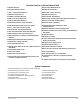


Wiring Description for the 24-Pin Connector
Pin col our Con nects to
1 Violet LED output (+)
2 Black/Gray Ignition coil or tach input
3 Green Armed output (Accessories) (-)
4 Orange Optional sensor input trigger zone (-)
5 Gray/Yellow Trunk trigger switch input (-)
6 Gray/Orange Door unlock output (+ or -)
7 White/Black Hood trigger switch input (-)
8 White PlainView 2 Valet Switch input (-)
9 Black twinlead Medallion Siren output
10 Black Ground for Dual-Zone Piezo and Optional Sensor
11 Yellow Optional airhorns or siren
12 Gray/Green Door lock output (+ or -)
13 Red Power for Dual-Zone Piezo and Optional Sensor
14 Gray/Violet Auxilliary A output (-)
15 Gray/Blue Auxilliary B output (-)
16 Gray/Red Auxilliary C output (-)
17 Brown Parking light output (+)
18 Brown Parking light output (+)
19 Blue/White Brake Light (+)
20 Red/White Battery (+) with 20-amp fuse
21 Brown/Red Interior light supply
22 Gray Door trigger (+ or -)
23 Black twinlead Medallion Siren output
24 White/Blue Remotely Adjustable Dual-Zone Piezo Sensor input
Wiring Description for the 4-Pin Connector
Pin Wire Colour Con nects to
1 Green/Blue Ignition Output (+ 12V)
2 White/Blue Starter Output (+ 12V)
3 White/Brown Ignition Input (+ 12V)
4 White/Green Starter Input (+12V)
2 In tel liGuard 7000/199