
- Directed Electronics, Inc.Network Device Installation Guide

4
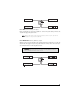
primary harness (H1) wire connection guide
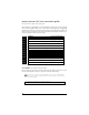
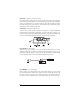
primary harness (H1) wiring diagram
The primary harness supplied with this unit is the standard 12-pin harness used. Two wires in the plug
are not used. The upgrade from this unit to a security system would simply require unplugging and
exchanging control units and connecting the necessary wires to the vehicle. The functions of all the wires
that are used in the primary harness are outlined in the following wiring diagram and the wire con-
nections are described in the wire connection guides.
___
___
___
___
___
___
___
___
___
___
___
___
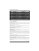
primary harness wire descriptions
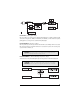
H1/1 ORANGE (-) Ground-When-Armed Output
This wire supplies a (-) 500 mA ground as long as the system is armed. This output ceases as soon as
the system is disarmed. The orange wire is pre-wired to control the starter kill relay.
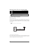
NNOOTTEE::
if using the H1/1 Orange wire to activate an add-on accessory such as window automation,
pager or voice module a 1Amp diode must be installed to ensure proper operation. Insert the diode as
shown in the following diagram.
IImmppoorrttaanntt!!
Never interrupt any wire other than the starter wire.
RED/WHITE (-) 200 mA Channel 2 Validity Output
RED (+) Constant Power Input
BROWN (-) Horn Honk Output
YELLOW Switched Ignition Input
BLACK (-) Chassis Ground Input
VIOLET No Function
BLUE (-) 200 mA Second Unlock Output
GREEN No Function
BLACK/WHITE (-) 200 mA Domelight Supervision Output
WHITE/BLUE (-) 200 mA Channel 3 Validity Output
WHITE (-) Light Flash Output
ORANGE (-) 500 mA Armed Output
H1/1
H1/2
H1/3
H1/4
H1/5
H1/6
H1/7
H1/8
H1/9
H1/10
H1/11
H1/12