
- Directed Electronics, Inc.Network Device Installation Guide

6
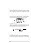
H1/6 BLUE (-) 200 mA Second Unlock Output
The H1/6 BLUE output is used for progressive unlock. A progressive unlock system unlocks the driver's
door when the unlock (disarm) button is pressed and unlocks the passenger doors if the unlock (disarm)
button is pressed again within 15 seconds after unlocking the driver's door. The BLUE wire outputs a
low current 200 mA (-) pulse on the second press of the unlock button of the transmitter. This negative
unlock output is used to unlock the passenger doors.
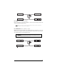
H1/8 BLACK (-) Chassis Ground Connection
Connect this wire to a clean, paint-free location (driver kick panel), or use a factory bolt that DOES
NOT have any vehicle component grounds attached to it. A screw should only be used when in con-
junction with a two-sided lock washer. Under dash brackets and door metal are not acceptable ground
points. It is recommended that all security components be grounded at the same location.
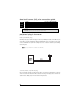
H1/9 YELLOW (+) Ignition Input
Connect this wire to the main ignition source. This input must show (+)12V with the key in run position
and during cranking. Make sure that this wire cannot be shorted to the chassis at any point. This wire
will trigger the system if the ignition is turned on before the unit is disarmed (doors unlocked with the
remote). It will also honk the vehicle’s horn and flash the parking lights (if connected).
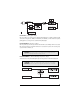
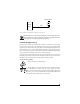
H1/10 BROWN (-) Horn Honk Output
This wire supplies a (-) 200 mA output that can be used to honk the vehicle horn. It outputs a single
pulse when locking the doors with the remote, and two pulses when unlocking with the remote. This
wire will also provide an output pulse for 30 seconds when the panic mode is activated. If the vehicle
has a (+) horn circuit, an optional relay can be used to interface with the system, as shown below.