Matrix 1 Installation Guide © 2005 Directed Electronics, Inc.
The Bitwriter® (p/n 998T) requires chip version 2.2 or newer to program this unit. Bitwriter®, Code Hopping®, Directed®, Doubleguard®, ESP®, FailSafe®, Ghost Switch®, Learn Routine™, Nite-Lite®, Nuisance Prevention® Circuitry, Revenger®, NPC®, Silent Mode™, Soft Chirp®, Stinger®, Valet®, VRS®, and Warn Away® are all Trademarks or Registered Trademarks of Directed Electronics, Vista, California.
Table of Contents What Is Included ..........................................................................................................................4 Primary Harness (H1) Wire Connection Guide ............................................................................4 Primary Harness Wiring Diagram.............................................................................................4 Primary Harness Wiring Instructions........................................................................
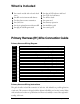
What Is Included ➤ ➤ ➤ ➤ ➤ ➤ One control module with on-board shock sensor One HF+ receiver/antenna with harness Two three-button remote transmitters One 514C siren One 12-pin primary harness with starter kill One plug-in Valet/Program switch ➤ ➤ ➤ ➤ ➤ ➤ ➤ One plug-in LED indicator with bezel One 3-pin door lock harness Two window decals One patent card One warranty registration One installation guide One owner’s guide Primary Harness (H1) Wire Connection Guide Primary Harness Wiring Diagram H1/1 ___ O
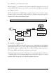
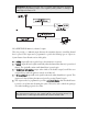
H1/1 ORANGE (-) ground-when-armed output This wire supplies a (-) ground as long as the system is armed. This output ceases as soon as the system is disarmed. The orange wire is pre-wired to control the 8618 starter kill relay. It can supply up to 500 mA of current. NOTE: If using the H1/1 ORANGE wire to activate an add-on accessory such as window automation, pager or voice module a 1Amp diode must be installed to ensure proper operation. Insert the diode as shown in the following diagram.
IMPORTANT! DO NOT connect this wire to a negative vehicle light flash wire before changing the programming jumper to the negative polarity position or damage to vehicle light circuit may occur. H1/3 WHITE/BLUE 200 mA (-) channel 3 output This wire provides a (-) 200 mA output whenever the transmitter button(s) controlling channel three is pressed.
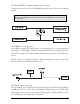
H1/4 BLACK/WHITE (-) 200 mA domelight supervision output Connect the H1/4 wire to the optional domelight supervision relay as shown in the following diagram: IMPORTANT! This output is only intended to drive a relay. It cannot be connected directly to the domelight circuit, as the output cannot support the current draw of one or more bulbs. H1/5 GREEN (-) door trigger input Most vehicles use negative door trigger circuits. Connect the green wire to a wire showing ground when any door is opened.
H1/7 VIOLET (+) door trigger input This type of dome circuit is used in many Ford products. Connect the violet wire to a wire that shows (+)12V when any door is opened. This wire will report Zone 3. NOTE: If using a door trigger wire that has a delay, Advanced Menu 2, feature 6 or the 998T Bitwriter can be used to turn Bypass Notification off.
H1/10 BROWN (+) siren output Connect this to the RED wire of the Revenger® siren. Connect the BLACK wire of the siren to (-) chassis ground, preferably at the same point you connect the control module’s BLACK ground wire. H1/11 RED (+)12V constant power input Before connecting this wire, remove the supplied fuse. Connect to the battery positive terminal or the constant 12V supply to the ignition switch. NOTE: Always use a fuse within 12 inches of the point you obtain (+)12V.
Door Lock Harness (H2), 3-PIN Connector H2/A ___ Green (-) Lock, (+) Unlock Output H2/B ___ Empty Unless Using 451M H2/C ___ Blue (-) Unlock, (+) Lock Output IMPORTANT! The door lock outputs are low current and should not be attached directly to any high current device; they are only to be used to activate relays NOTE: For detailed instructions about connecting to the vehicle’s power door lock systems, refer to the Door Lock Wiring guide (Document No.
DIA-41 Valet/Program Switch, 2-Pin BLUE Plug The Valet/Program button should be accessible from the driver’s seat. It plugs into the BLUE port on the side of the unit. Since the system features Valet® by using the remote transmitter, the button can be well hidden. Consider how the button will be used before choosing a mounting location. Check for rear clearance before drilling a 9/32-inch hole and mounting the button.
Mounting the Receiver/Antenna Receiver/antenna position should be discussed with the vehicle owner prior to installation, since the antenna may be visible to the vehicle’s operator. The best location for the receiver/antenna is centered high on either the front or rear windshield. For optimal range, the antenna should be mounted vertically. It can be mounted horizontally in relation to the windshield or under the dashboard away from metal, but range will be diminished.
On-Board Dual-Stage Shock Sensor There is a dual-stage shock sensor inside the control unit. Adjustments are made via the rotary control as indicated in the diagram. Since the shock sensor does not work well when mounted firmly to metal, we do not recommend screwing down the control module. The full trigger of the on-board shock sensor reports Zone 2. (See Table of Zones section of this guide.
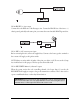
Programming Jumper Light Flash Jumper This jumper is used to determine the light flash output. In the (+) position, the on-board relay is enabled and the unit will output (+)12V on the WHITE wire, H1/2. In the (-) position, the onboard relay is disabled. The WHITE wire, H1/2, will supply a 200 mA (-) output suitable for driving factory parking light relays. NOTE: For parking light circuits that draw 10 amps or more, the jumper must be switched to a (-) light flash output.
H1/6 Blue wire, all trigger inputs except the door trigger input will remain bypassed until 5 seconds after ground is removed from the BLUE wire.
1. Open a door. (The H1/5 GREEN wire or the H1/7 VIOLET wire must be connected.) 2. Ignition. Turn the ignition on, then back off: (The H1/9 YELLOW wire must be connected.) 3. Select a Menu. Press and HOLD the Valet/Program switch: (The Valet/Program switch must be plugged into the blue port.) After three seconds the siren will chirp once indicating entry to the Basic Features Menu #1. If this is the menu you wish to access, release the button and go on to Step 4.
To access another feature in the same menu: 1. Press and release the Valet/Program switch the number of times necessary to advance from the feature you just programmed to the next one you want to program. 2. Then press the Valet/Program switch once more and HOLD it. For example, if you just programmed the third feature in the menu and you would like to program the seventh feature in the menu, you would press and release the Valet/Program switch four times and then press it once more and HOLD it.
System Features Menus Menu #1 - Basic Features Items in bold text have been programmed to the default setting at the factory. Feature Number One Chirp Setting Two-Chirp Setting 1-1 Active arming Passive arming 1-2 Chirps ON Chirps OFF 1-3 Ignition controlled door locks ON Ignition controlled door locks OFF 1-4 Active locking only Passive locking 1-5 Panic with ignition on No Panic with ignition on 1-6 0.8 second door lock pulses 3.5 second door lock pulses/0.4 sec.
Feature Descriptions The features of the system are described below. Features that have additional settings that can be selected only when programming with the 998T Bitwriter are indicated by the following icon: Menu #1 - Basic Features 1-1 ACTIVE/PASSIVE ARMING: When active arming is selected, the system will only arm when the transmitter is used. When set to passive, the system will arm automatically 30 seconds after the last door is closed.
setting is 0.8 second door lock pulses. For some vehicles a 0.4 second pulse duration is required to prevent the windows from moving. 1-7 FORCED PASSIVE ARMING ON/OFF: To use this feature, passive arming must be selected in step 1-1. When turned on, forced passive arming will ensure that the system will passively arm, even if a zone is left open or invalid. Forced passive arming occurs one hour after the ignition is turned off.
2-3 FALSE ALARM CONTROL TECHNOLOGY (FACT) ON/OFF: FACT stops repeated triggering of the same zone. If one zone is triggered three times in one hour, that zone is bypassed for one hour, starting from the time of the third trigger. During that hour, if the system detects a trigger on that zone again, the system resets the one hour timer. If one hour passes and the zone has not triggered again, the zone is activated and can trigger the system again.
2-9 DOUBLE/SINGLE PULSE LOCK: Some vehicles require two pulses on a single wire to unlock the doors. When the double pulse unlock feature is turned on, the GREEN H2/A wire will supply two negative pulses instead of a single pulse. At the same time, the BLUE H2/C wire will supply two positive pulses instead of a single pulse. This makes it possible to directly interface with double pulse vehicles without any extra parts.
3. Select the receiver channel: Press and release the Valet/Program button the number of times necessary to access the desired channel. NOTE: If adding a remote, a button must be taught to the unit in the Channel 1 or Channel 5 position prior to programming other channels. Press and hold the Valet/Program button once more. The siren will chirp and the LED will blink the number of times corresponding to the channel that is accessed.
Channels 4-6 (available only when using a Radar Master remote) Channels 4 through 6 are used to assign the arm, disarm and panic functions to separate buttons on the remote control. These channels are only available when using an optional Radar Master remote. (See Transmitter Configurations section of this guide.) Teaching a transmitter button to Channel 4 erases all previous programming from the transmitter’s memory.
..........................operates ......................Arm/Disarm/Panic .............................operates ......................Channel 2 .............................operates ......................Channel 3 4-Button Transmitter Configuration This system has a 4-button transmitter configuration that can be used when upgrading to an optional 4-button remote. This configuration can be programmed to a 4-button transmitter using Channel 8 of the Transmitter/Receiver Learn Routine.
System Status Chirps Action Number of Chirps Description Arm 1 System armed Arm 1 (3 second delay), 1 System armed with Bypass Notification Disarm 2 System disarmed Disarm 4 System disarmed with Tamper Alert Disarm 5 System disarmed FACT active Table of Zones Zone No. Trigger type Input description 1 Instant H1/6 BLUE - Connect to optional hood/trunk pins. 2 On-board shock sensor Heavy impact detected by the on-board shock sensor.
2. Turn on the ignition. 3. Release the Valet/Program switch. 4. Press and release the Valet/Program switch within 5 seconds. The LED will flash in groups indicating the last two zones that triggered the unit. The LED will flash for one minute or until the ignition is turned off. NOTE: The Warning Zone triggers are not stored to memory and will not be reported.
Optional Vehicle Recovery System (VRS) VRS is an optional feature designed to disable a vehicle during a carjacking event. It must be programmed in the features menu and the Failsafe Starter Kill must be installed for it to work properly. For operational instructions when testing VRS refer to the owner's manual. False Alarm Control Technology (FACT) FACT requires that you change the way you test the system, as FACT will bypass an input zone for 60 minutes.
Troubleshooting Starter kill doesn’t work. ➤ Is the correct starter wire being interrupted? If the car starts when the starter kill relay is completely disconnected, the wrong starter wire has been cut and interrupted. ➤ YELLOW wire is not connected to true ignition. It is connected to an accessory circuit. Shock sensor doesn’t trigger the alarm. ➤ Has the FACT system been triggered? If so, you will hear five chirps when disarming.
(+) LIGHT FLASH OUTPUT (DEFAULT) (-) LIGHT FLASH OUTPUT LIGHT FLASH JUMPER DIA-436 Wiring Quick Reference Guide 30 © 2005 Directed Electronics, Inc.