Model 740T Installation Guide © 2004 Directed Electronics, Inc.
table of contents what is included . . . . . . . . . . . . . . . . . . . . . . . . . . . . . . . . . . . . . . . . . . . . . . . . . . . . . . . . . . . . . . . . 3 primary harness (H1) wire connection guide . . . . . . . . . . . . . . . . . . . . . . . . . . . . . . . . . . . . . . . . . . . . . 3 door lock harness (H2) wire connection guide . . . . . . . . . . . . . . . . . . . . . . . . . . . . . . . . . . . . . . . . . . . . 8 type A: positive (+) 12V pulses from the switch to the factory relays. . . .
what is included ■ The control module ■ A high-powered siren ■ Two 3-button remote transmitters ■ The 12-pin primary harness ■ The plug-in LED system status indicator ■ The 3-pin door lock harness ■ The plug-in Valet/Program switch ■ The plug-in starter interrupt harness ■ An on-board zone 2 impact sensor primary harness (H1) wire connection guide H1/1 H1/2 H1/3 H1/4 H1/5 H1/6 H1/7 ______ ______ ______ ______ ______ ______ ______ ORANGE (-) 500 mA GROUND-WHEN-ARMED OUTPUT WHITE (+/-) SELECTABL
H1/2 WHITE (+/-) selectable light flash output As shipped, this wire should be connected to the (+) parking light wire. If the light flash polarity jumper inside the control module is moved to the opposite position (see Internal Programming Jumper section of this guide), this wire supplies a (-) 200 mA output. This is suitable for driving (-) light control wires in Toyota, Lexus, BMW, some Mitsubishi, some Mazda, and other model cars.
H1/4 BLACK/WHITE (-) interior light illumination output Connect the H1/4 BLACK/WHITE wire to an optional relay for interior light illumination (pp/n 8617 or standard automotive SPDT relay). IMPORTANT! This output is only intended to drive a relay. It cannot be connected directly to the domelight circuit, as the output is not able to support the current draw of one or more light bulbs. H1/5 GREEN (-) door trigger input, zone 3 Most vehicles use negative door trigger circuits.
is detected within 5 seconds of transmission, the sensors and the multiplex trigger input on the BLUE wire will be shunted until 5 seconds after the ground is removed. This allows the customer to access the trunk, remote start the vehicle, or roll the windows down without first disarming the alarm. (See Bypassing Sensor Inputs section of this guide.) H1/7 VIOLET (+) door trigger input, zone 3 This wire is used in vehicles that have a positive (+) switched dome light circuit.
H1/10 BROWN (+) siren output Connect this to the red wire of the siren. Connect the black wire of the siren to (-) chassis ground, preferably at the same point you connect the control module’s black ground wire. H1/11 RED (+)12V constant power input Before connecting this wire, remove the supplied fuse. Connect to the positive battery terminal or the constant 12V supply to the ignition switch. NOTE: Always use a fuse within 12 inches of the point you obtain (+)12V power.
door lock harness (H2) wire connection guide H2/1 H2/2 ______ ______ H2/3 ______ GREEN (-) LOCK, (+) UNLOCK OUTPUT OPEN UNLESS USING 451M BLUE (+) LOCK, (-) UNLOCK OUTPUT This security system can control two common power door lock types without any additional parts! With certain vehicles, or if an actuator is to be installed, either a 451M Door Lock Relay Satellite or two relays will be required.
Reconnect the wire and look for another wire. Many domestically-made GM vehicles use Type A locks. However, many more GM vehicles are Type C than in previous years. The full-size pickups (1989-later), many of the S10 Blazers, the Corvette, '95 Cavalier/Sunfire 1993 and newer, Camaro/Firebird all use Type C door locks, and cannot be controlled without a 451M! Almost all domestically-built Fords are Type C. Ford builds almost no Type A systems. Chrysler builds both Type A and Type C, so test carefully.
type B: negative (-) pulses from the switch to the factory relays This system is common in many Toyota, Nissan, Honda, and Saturn models, as well as Fords with remote-controlled door lock/unlock (some other Fords also use Type B). The switch will have three wires on it, and one wire will test ground all the time. One wire will pulse (-) when the switch locks the doors, and the other wire will pulse (-) when the switch unlocks the doors. This type of system is difficult to mistake for any other type.
type C: reversing polarity Interfacing with a reversing polarity system requires either two relays or one 451M (not included). It is critical to identify the proper wires and locate the master switch to interface properly. Locate wires that show voltage on lock and unlock. Cut one of the suspect wires and check operation of the locks from both switches. If one switch loses operation in both directions and the other switch operates in one direction only, you have located one of the target wires.
type D: after-market actuators In order for this system to control one or more after-market actuators, a 451M or two relays (optional) are needed. Vehicles without factory power door locks require the installation of one actuator per door. This requires mounting the door lock actuator inside the door. Other vehicles may only require one actuator installed in the driver's door if all door locks are operated when the driver's lock is used.
type E: mercedes-benz and audi (1985 and newer) Door locks are controlled by an electrically activated vacuum pump. Some Mercedes and Audi models use a Type D system. Test by locking doors from the passenger key cylinder. If all the doors lock, the vehicle's door lock system can be controlled with just two relays (optional). The control wire can be found in either kick panel and will show (+)12V when doors are unlocked and (-) ground when doors are locked. To interface, see diagram below.
type F: one-wire system This system usually requires a negative pulse to unlock, and cutting the wire to lock the door. In some vehicles, these are reversed. It is found in late-model Nissan Sentras, some Nissan 240SX, and Nissan 300ZX 1992 and later. It is also found in some Mazda MPV's and some Mitsubishi's. One relay (optional) is used to interface to this type of system as follows: type G: positive (+) multiplex This system is most commonly found in Ford, Mazda, Chrysler and GM vehicles.
single-resistor type If one resistor is used in the door lock switch/key cylinder, the wire will pulse (+)12V in one direction and less than (+)12V when operated in the opposite direction. two-resistor type If two resistors are used in the factory door lock switch/key cylinder, the switch/key cylinder will read less than (+)12V in both directions. determining the proper resistor values To determine the resistor values, the door lock switch/key cylinder must be isolated from the factory door lock system.
type H: negative (-) multiplex The system is most commonly found in Ford, Mazda, Chrysler and GM vehicles. The door lock switch or door key cylinder may contain either one or two resistors. When interfacing with this type of door lock system, two relays or a 451M must be used. single-resistor type If one resistor is used in the door lock switch/key cylinder, the wire will pulse ground in one direction and resistance to ground when operated in the opposite direction.
starter interrupt harness (H3) wire connection guide H3/1 H3/2 ______ ______ BLACK STARTER INTERRUPT INPUT BLACK STARTER INTERRUPT OUTPUT H3/1 and H3/2 BLACK starter interrupt wires Use one of these wire as a starter interrupt input and the other as a starter interrupt output wire NOTE: These two black wires are interchangeable. plug-in LED and valet/program switch The LED and the Valet/Program switch both plug into the control module.
internal programming jumper TO CHANGE JUMPER SETTINGS DRW-298 (-) Light flash output (+) Light flash output (default) light flash jumper This jumper is used to determine the light flash output. In the (+) position, the on-board relay is enabled and the unit will output (+)12V on the H1/2 WHITE wire. In the (-) position, the on-board relay is disabled. The H1/2 WHITE wire will supply a (-) 200 mA output suitable for driving factory parking light relays. To access the jumper, open the control module.
screwing down the control module. We recommend mounting the control module to a large wiring loom. NOTE: When adjusting the sensor, it must be mounted in the same location where it will be after the installation is completed. Adjusting the sensor and then relocating the module requires readjustment. bypassing sensor inputs There are times when you need to temporarily bypass all sensor inputs to the unit, such as when remote starting the vehicle.
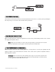
1. Open a door. (The GREEN wire, H1/5, or the VIOLET, H1/7 must be connected.) 2. Key. Turn the ignition on. (The H1/9 YELLOW switched ignition input must be connected.) 3. Select the receiver channel. Press and release the Valet®/Program switch the number of times necessary to access the desired channel. Once you have selected a channel, press and HOLD the Valet®/Program switch once more.
5. Release. Once the code is learned, the Valet®/Program button can be released. You can advance from one channel to another by releasing the Valet® /Program button and tapping it to advance channels and then HOLDING it. For example, if you want to program Channel Three after programming Channel One, release the Valet®/Program button. Press it twice and release it to advance to Channel Three. Then press it once more and HOLD it.
operating settings remote control code learning Many of the operating settings of this unit are programmable. They can be changed whenever necessary through Operating Settings Remote Control Code Learning. The Valet®/Program push-button switch, plugged into the blue port, is used together with a programmed transmitter to change the settings. The operating settings dictate how the unit operates. It is possible to access and change any of the feature settings using the Valet®/Program switch.
5. Release. Release the Valet®/Program switch. To access another feature: You can advance from feature to feature by pressing and releasing the Valet®/Program switch the number of times necessary to get from the feature you just programmed to the feature you wish to access. For example, if you just programmed Feature 1 and you want to program Feature 2: 1. Release the Valet®/Program switch. 2. Press and release the Valet/Program switch once to advance from Feature 1 to Feature 2. 3.
feature descriptions 1 ACTIVE/PASSIVE ARMING: When active arming is selected, the system will only arm when the transmitter is used. When set to passive, the system will arm automatically 30 seconds after the last door is closed. Passive arming is indicated by the rapid flashing of the LED when the last protected entry point is closed. 2 CONFIRMATION CHIRPS ON/OFF: This feature controls the chirps that confirm the arming and disarming of the system.
9 Double Pulse Lock. Selectable 2 pulse door lock output to operate vehicle equipped with factory “deadbolt”.
table of zones When using the Diagnostic functions, use the Table of Zones to see which input has triggered the system. It is also helpful in deciding which input to use when connecting optional sensors and switches. ZONE NO. TRIGGER TYPE INPUT DESCRIPTION 1 Multiplexed H1/6 BLUE wire. Connects to optional hood/trunk pins or an optional sensor. Inputs longer than 0.8 seconds will instantly trigger the full alarm sequence and report Zone 1.
■ Door input does not respond with the progressive trigger, but with immediate full alarm: Does the LED indicate that the trigger was caused by the impact sensor? (See Table of Zones section of this guide.) The impact sensor, if set to extreme sensitivity, may be detecting the door unlatching before the door switch sends its signal. Reducing the sensitivity can solve this problem.
© 2004 Directed Electronics, Inc.
© 2004 Directed Electronics, Inc.