DIRECTED ENERGY, INC. PDG-2515/2520 Digital Delay and Pulse Generator OPERATING MANUAL www.directedenergy.
THE PULSE OF THE FUTURE
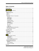
PDG-2515/2520 Operating Manual Table of Contents Table of Contents................................................................................................... i List of Figures ...................................................................................................... iv Safety Warning ..................................................................................................... v PDG-2515 Operating Manual ............................................................................
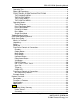
PDG-2515/2520 Operating Manual Operating Tips...................................................................................................8 Power-Up Procedures .......................................................................................9 FRONT PANEL OPERATING INSTRUCTIONS ...............................................9 THE CHANNEL MENU ..................................................................................9 THE OUTPUT MENU ........................................................
PDG-2515/2520 Operating Manual Cover Removal ............................................................................................24 General Operating Precautions ...................................................................24 Servicing Safety Summary ..............................................................................25 PREPARATION FOR USE..............................................................................25 General ..........................................................
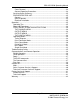
PDG-2515/2520 Operating Manual List of Figures Figure 1 Logic & Polarity Functional Diagram .....................................................11 Figure 2 Timing Diagram ....................................................................................12 Figure 3 Example 1: Pulse Generator Mode.......................................................13 Figure 4 Example 2: Pulse Generator Mode.......................................................13 Figure 5 Example: Pulse Count Mode .....................
PDG-2515/2520 Operating Manual Safety Warning SAFE OPERATING PROCEDURES AND PROPER USE OF THE EQUIPMENT ARE THE RESPONSIBILITY OF THE USER OF THIS SYSTEM. Directed Energy, Inc. (DEI) provides information on its products and associated hazards, but it assumes no responsibility for the after sale operation and safety practices. Users are responsible for reading and understanding all safety precautions listed in this manual prior to operation of the equipment.
PDG-2515/2520 Operating Manual PDG-2515 Operating Manual Quick Start Guide This quick-start guide provides a step-by-step guide to manually operating the PDG-2515. Please refer to the appropriate sections of the manual for additional instructions and guidelines. The SAFETY warnings in the manual must be read and understood prior to operating the PDG-2515. What’s In The Box? 1ea. PDG-2515 Digital Delay & Pulse Generator 1ea. Power Cord 2ea. 50 Ohm Coaxial Output Cable 1ea.
PDG-2515/2520 Operating Manual Output Button The output button enables/disables the pulse output. Menu Button This button is for navigating the PDG-2515 menus. Enter Button Used for variables that will be permanently stored in the unit or require setup times internal to the PDG-2515. When a question mark appears after the variable, the enter button will “confirm” or in some cases save that particular setting.
PDG-2515/2520 Operating Manual X10 button once to increment it to 250ns, then rotate the encoder wheel to increase it to 300ns. At this point, pressing the X10 button again would increase the delay to 3.00us, pressing it again increments it to 30.0us, etc. An additional function is that if it is held while changing ANY frequency value, after multiplying the value by a factor of ten, if the encoder is moved it will increase/decrease at a much faster rate.
PDG-2515/2520 Operating Manual The PDG-2515 accepts input voltages of 90-264VAC, 47-63Hz. Example Setup The default setup is 1 kHz, with zero delay and 100 us pulse on both channels. The pulse in not inverted and the pulse mode is in continuous pulse generation mode which means that pulse count is not available. By pressing the OUTPUT button on the front panel you will see these pulses on the respective outputs.
PDG-2515/2520 Operating Manual Product Overview Description The PDG-2515 is a two channel digital delay/pulse generator. Each channel offers independently adjustable delay and width, with 25 nanosecond resolution. Up to five user configurations may be stored in internal non-volatile memory, and recalled through the easy to understand front panel. Functions & Features Delay And Width and Duty Cycle. Each channel provides independently adjustable delay and width, with 25ns resolution.
PDG-2515/2520 Operating Manual Specifications PARAMETER OUTPUTS Output Channels Value Delay Range Pulse Width Range Delay And Pulse Width Resolution Accuracy (Delay and Pulse Width) Time Base Delay Jitter (1st Sigma) Trigger Delay (External Trigger to SYNC (T0) Output Internal Throughput Delay (SYNC (T0) To Output 1 Or Output 2 Rising Edge) Output Rise & Fall Times (Into 50Ω) Over/undershoot Amplitude Output Connectors INTERNAL RATE GENERATOR Modes Rate Resolution Accuracy (Continuous, Pulse Count, Outp
PDG-2515/2520 Operating Manual Applications The versatile functionality of the PDG-2515 makes it ideal for the needs of numerous applications as a small bench top instrument. The delay resolution and width resolution of each channel allow a unique ability to offset control signals, coupled with ability to logically manipulate the outputs together to form gate signals or specific waveforms make automation of testing and control an easier process.
PDG-2515/2520 Operating Manual equipment when making connections in high voltage or high current circuits. Discharge high voltage capacitors after removing power. Servicing Safety Summary DEI strongly recommends that all repairs and adjustments be performed by factory qualified personnel. DEI will not be responsible for personal injury or damage to the pulse generator that occurs during repair by any party other than the factory.
PDG-2515/2520 Operating Manual change is accomplished by using the encoder while holding the 10X button down. Power-Up Procedures The unit should be powered up using the following procedures: Connect OUT 1 and/or OUT 2 to an appropriate load using 50 Ohm coaxial cable (See Section 6.0). Plug the AC power cord into the PDG-2515, and into an appropriate AC socket. Turn on the PDG-2515 by pressing the power button on the rear of the unit located above the power entry . Configure the unit from the front panel.
PDG-2515/2520 Operating Manual the contrast settings of the unit. The operating modes will be discussed in more detail in section 9.0. Enabling and disabling a channel can also happen on the fly in pulse generation and Divide By N modes. In pulse count mode this needs to be set before hand so the unit does not sit in an unknown state if it has not finished it’s count set, therefore, the unit will not allow it to be changed while pulsing.
PDG-2515/2520 Operating Manual Figure 1 Logic & Polarity Functional Diagram THE CONFIGS MENU The CONFIGS MENU allows the user to save or load up to 5 different configurations. After selecting the appropriate configuration to either load or save (1 through 5) hit the ENTER button and the configuration of the unit will be saved. If the user tries to load a configuration that has not been saved yet, the unit will send an error message of “Not Valid Config” and nothing will be loaded.
PDG-2515/2520 Operating Manual Figure 2 Timing Diagram Please note that in external trigger mode, all outputs are delayed from the leading edge of the external trigger signal. Pulse Generator Mode In Pulse Generator Mode, the PDG-2515 generates pulses at the specified frequency denoted in the CHANNEL MENU (changing the frequency on either channel will change the frequency on both channels simultaneously – the frequencies are not independent in this mode).
PDG-2515/2520 Operating Manual Figure 3 Example 1: Pulse Generator Mode Figure 4 Example 2: Pulse Generator Mode Pulse Count Mode In Pulse Count Mode, the PDG-2515 generates a series of pulses, the number of which is set by the PULSE CT variables on the respective channel menu. When the number of pulses output on an output channel equals the number set, the output of that channel is automatically disabled and the output LED will reflect this Page 13 MNPDG2515-2520R0.doc © 2004 Directed Energy, Inc.
PDG-2515/2520 Operating Manual The PULSE CT variable for each channel can be set to any value between 1 and 65,535. In setting the PULSE CT, the x10 button will increase this number by a factor of ten and the encoder wheel will increase/decrease the number of pulses incrementally by one. For example, to set the count to 1,500, first set the count to 15 using the encoder wheel, then press the X10 button two times. The first press will increment the count to 150, and the second to 1,500.
PDG-2515/2520 Operating Manual Be aware that coming out of this mode, if any variables are out of range by going into a mode that conflicts with these settings, the channel/channels will be set back to the default values. Figure 6 Example 1: Divide by N Mode Figure 7 Example 2: Divide by N Mode Burst Mode In Burst Mode, a set number of pulses (the burst packet) are output from OUT1. Each burst packet is sent at the packet frequency.
PDG-2515/2520 Operating Manual frequency at a limited duty cycle and cutoff any length of burst after that length of time). The software will not check to check timing constraints in this mode, meaning that if the timing if violated, the output may be erroneous and not predictable (only while the constraints are violated – for example if the number of bursts exceeds the time period of the packet frequency this would violate the hardware of the unit).
PDG-2515/2520 Operating Manual Troubleshooting Guide No power LED or screen does not come up. Pulse exhibits excessive ringing. Frequency limits. Check power source, power switch (located on rear of unit). Check load impedance. Check duty cycle of EACH channel, both channels must be within the specifications of the unit to increase the frequency. Note that duty cycle of a channel is the addition of the pulse width and the delay. Pulse Width limits. Check the frequency and duty cycle.
PDG-2515/2520 Operating Manual PDG-2520 Operating Manual Quick Start Guide This quick-start guide provides a step-by-step guide to manually operating the PDG-2520. Please refer to the appropriate sections of the manual for additional instructions and guidelines. The SAFETY warnings in the manual must be read and understood prior to operating the PDG-2520. What’s In The Box? 1ea. PDG-2520 Digital Delay & Pulse Generator 1ea. Power Cord 2ea. 50 Ohm Coaxial Output Cable 1ea.
PDG-2515/2520 Operating Manual Output Button The output button enables/disables the pulse output. Menu Button This button is for navigating the PDG-2520 menus. Enter Button Used for variables that will be permanently stored in the unit or require setup times internal to the PDG-2520. When a question mark appears after the variable, the enter button will “confirm” or in some cases save that particular setting.
PDG-2515/2520 Operating Manual X10 button once to increment it to 250ns, then rotate the encoder wheel to increase it to 300ns. At this point, pressing the X10 button again would increase the delay to 3.00us, pressing it again increments it to 30.0us, etc. An additional function is that if it is held while changing ANY frequency value, after multiplying the value by a factor of ten, if the encoder is moved it will increase/decrease at a much faster rate.
PDG-2515/2520 Operating Manual The PDG-2520 accepts input voltages of 90-264VAC, 47-63Hz. Example Setup The default setup is 1 kHz, with zero delay and 100 us pulse on both channels. The pulse in not inverted and the pulse mode is in continuous pulse generation mode which means that pulse count is not available. By pressing the OUTPUT button on the front panel you will see these pulses on the respective outputs.
PDG-2515/2520 Operating Manual Product Overview Description The PDG-2520 is a four channel digital delay/pulse generator. Each channel offers independently adjustable delay and width, with 25 nanosecond resolution. Up to five user configurations may be stored in internal non-volatile memory, and recalled through the easy to understand front panel. Functions & Features Delay And Width and Duty Cycle. Each channel provides independently adjustable delay and width, with 25ns resolution.
PDG-2515/2520 Operating Manual Specifications PARAMETER OUTPUTS Output Channels Value Delay Range Pulse Width Range Delay And Pulse Width Resolution Accuracy (Delay and Pulse Width) Time Base Delay Jitter (1st Sigma) Trigger Delay (External Trigger to SYNC (T0) Output Internal Throughput Delay (SYNC (T0) To Output 1 Or Output 2 Rising Edge) Output Rise & Fall Times (Into 50Ω) Over/undershoot Amplitude Output Connectors INTERNAL RATE GENERATOR Modes Rate Resolution Accuracy (Continuous, Pulse Count, Outp
PDG-2515/2520 Operating Manual Applications The versatile functionality of the PDG-2520 makes it ideal for the needs of numerous applications as a small bench top instrument. The delay resolution and width resolution of each channel allow a unique ability to offset control signals, coupled with ability to logically manipulate the outputs together to form gate signals or specific waveforms make automation of testing and control an easier process.
PDG-2515/2520 Operating Manual equipment when making connections in high voltage or high current circuits. Discharge high voltage capacitors after removing power. Servicing Safety Summary DEI strongly recommends that all repairs and adjustments be performed by factory qualified personnel. DEI will not be responsible for personal injury or damage to the pulse generator that occurs during repair by any party other than the factory.
PDG-2515/2520 Operating Manual change is accomplished by using the encoder while holding the 10X button down. Power-Up Procedures The unit should be powered up using the following procedures: Connect OUTPUTs to an appropriate load using 50 Ohm coaxial cable (See Section 6.0). Plug the AC power cord into the PDG-2520, and into an appropriate AC socket. Turn on the PDG-2520 by pressing the power button on the rear of the unit located above the power entry . Configure the unit from the front panel.
PDG-2515/2520 Operating Manual modes will be discussed in more detail in section 9.0. Enabling and disabling a channel can also happen on the fly in all modes except Burst Mode. In Burst mode, enabling/disabling the channels is not available and Channel 1 and 2 are enabled, Channel 3 and 4 are disabled automatically. When the mode is switched from Burst mode, the enable/disable settings will return to where they were previous to Burst mode.
PDG-2515/2520 Operating Manual Figure 9 Logic & Polarity Functional Diagram THE CONFIGS MENU The CONFIGS MENU allows the user to save or load up to 5 different configurations. After selecting the appropriate configuration to either load or save (1 through 5) hit the ENTER button and the configuration of the unit will be saved. If the user tries to load a configuration that has not been saved yet, the unit will send an error message of “Not Valid Config” and nothing will be loaded.
PDG-2515/2520 Operating Manual Figure 10 Timing Diagram Please note that in external trigger mode, all outputs are delayed from the leading edge of the external trigger signal. Pulse Generator Mode In Pulse Generator Mode, the PDG-2520 generates pulses at the specified frequency denoted in the CHANNEL MENU (changing the frequency on either channel will change the frequency on both channels simultaneously – the frequencies are not independent in this mode).
PDG-2515/2520 Operating Manual Figure 11 Example 1: Pulse Generator Mode Figure 12 Example 2: Pulse Generator Mode with logic Pulse Count Mode In Pulse Count Mode, the PDG-2520 generates a series of pulses, the number of which is set by the PULSE CT variables on the respective channel menu. When the number of pulses output on an output channel equals the number set, the output of that channel is automatically disabled and the output LED will reflect this Page 30 MNPDG2515-2520R0.
PDG-2515/2520 Operating Manual The PULSE CT variable for each channel can be set to any value between 1 and 65,535. In setting the PULSE CT, the x10 button will increase this number by a factor of ten and the encoder wheel will increase/decrease the number of pulses incrementally by one. For example, to set the count to 1,500, first set the count to 15 using the encoder wheel, then press the X10 button two times. The first press will increment the count to 150, and the second to 1,500.
PDG-2515/2520 Operating Manual Be aware that coming out of this mode, if any variables are out of range by going into a mode that conflicts with these settings, the channel/channels will be set back to the default values. Also be aware that channels 1 and 3 stay synchronized and channels 2 and 4 must have the same value for N. The delays and pulse widths on these channels are all independent. Figure 14 Example 1: Divide by N Mode Figure 15 Example 2: Divide by N Mode Page 32 MNPDG2515-2520R0.
PDG-2515/2520 Operating Manual Burst Mode In Burst Mode, a set number of pulses (the burst packet) are output from OUT1. Each burst packet is sent at the packet frequency. The burst packet will start ONE period of the burst packet frequency after the rising edge of the packet frequency (OUT 2 will ALWAYS output the packet frequency at a limited duty cycle and cutoff any length of burst after that length of time).
PDG-2515/2520 Operating Manual Figure 17 Example: Single Shot Mode Page 34 MNPDG2515-2520R0.doc © 2004 Directed Energy, Inc.
PDG-2515/2520 Operating Manual Troubleshooting Guide No power LED or screen does not come up. Pulse exhibits excessive ringing. Frequency limits. Check power source, power switch (located on rear of unit). Check load impedance. Check duty cycle of EACH channel, both channels must be within the specifications of the unit to increase the frequency. Note that duty cycle of a channel is the addition of the pulse width and the delay. Pulse Width limits. Check the frequency and duty cycle.
PDG-2515/2520 Operating Manual Communications and Remote Operation: The PDG25xx series of pulse generators have the option of a communications interface. The options are RS232 or GPIB interface. Both interfaces take the same ascii based command set, although the strings are terminated differently. The unit will reply at least one byte on every command with the exception of the changing of the GPIB address, and the changing of the baud rate.
PDG-2515/2520 Operating Manual Reply: The reply generated will be either response to the data sent to the unit, as in a query, or an error code. The error code will be prefaced by a ‘#’ and then the ascii code itself. The codes are explained below. The error code, whether it is 0 (which indicates NO ERROR) or a valid error is prefaced by the ‘#’ character to distinguish the data from a valid reply.
PDG-2515/2520 Operating Manual 2 3 READ,WRITE READ,WRITE 4 READ,WRITE 1 READ,WRITE 2 0 1 x READ,WRITE READ,WRITE READ,WRITE READ,WRITE FIRM HDWR LOAD SAVE VERS VERS x x N/A N/A WRITE WRITE READ READ GPIB SERL ADDR BAUD x 1 2 3 4 5 6 7 READ,WRITE READ,WRITE FIRM VERS N/A READ TRIG STAT SYNC SYST COMM CONF SET MODE TO DIVIDE-BY-N MODE SET MODE TO BURST MODE SET MODE TO INTERNAL SINGLE SHOT SET CHANNEL TO INTERNAL TRIGGER SET CHANNEL TO EXTERNAL TRIGGER DISABLE PULSING ENABLE PULSING SE
PDG-2515/2520 Operating Manual Error Set: First Byte # # # # # # # # # # # # # # # # # Decimal 0 1-63 64 65 66 67 68 69-111 112 113 114 115 116 117-119 120 121 122-255 Hex 0x00 0x01-0x3A 0x40 0x41 0x42 0x43 0x44 0x45-0x6A 0x70 0x71 0x72 0x73 0x74 0x75-0x77 0x78 0x79 0x80-0xFF Error NO ERROR RESERVED DATA IS OUT OF RANGE FREQUENCY IS DC LIMITED PULSEWIDTH IS FREQUENCY LIMITED DELAY IS FREQUENCY LIMITED INVALID CONFIGURATION RESERVED UNRECOGNIZED WORD BAD STRING FORMAT BAD DATA FORMAT UNRECOGNIZED PARSE E
PDG-2515/2520 Operating Manual Contact DEI We want to hear from you! Directed Energy, Inc. provides a standard line of High Voltage Pulse Generators, Laser & Diode Drivers, and Test & Measurement Equipment. Additionally, DEI has the capability to provide custom modules and products to fit your volume or OEM application. Web Visit our web site at www.DirectedEnergy.com Also visit these other IXYS companies • IXYS – www.IXYS.com • Clare – www.Clare.com • Micronix – www.ClareMicronix.com • Westcode – www.
PDG-2515/2520 Operating Manual Factory Service & Support This product has been designed to provide simple trouble-free use by qualified technical personnel, under normal operating conditions. In the event that you require technical support and/or product service our technical support staff is available to assist you. You can contact our team as noted previously. DEI’s technical support is available as follows.
PDG-2515/2520 Operating Manual Warranty Directed Energy, Inc. (DEI) warrants equipment it manufactures to be free from defects in materials and factory workmanship under conditions of normal use, and agrees to repair or replace any standard product that fails to perform as specified within one year after date of shipment to the original owner. OEM, modified and custom products are warranted, as stated above, for ninety (90) days from date of shipment to the original owner.