24923 ➤Owner’s/Installation Guide
limited lifetime consumer warranty Directed Electronics, Inc. (hereinafter "Directed") promises to the original purchaser to repair or replace with a comparable reconditioned Directed DIY remote start unit if this Directed DIY remote start unit (hereinafter "Unit"), excluding without limitation, any remote transmitters or associated accessories, proves defective in materials or workmanship under normal use for the life of the vehicle which the Unit is originally installed.
OR IN CONNECTION WITH THE INSTALLATION, USE, IMPROPER USE, OR INABILITY TO USE, THE PRODUCT, EVEN IF THE PARTY HAS BEEN ADVISED OF THE POSSIBILITY OF SUCH DAMAGES. SOME STATES DO NOT ALLOW THE EXCLUSION OF LIMITATION OF INCIDENTAL OR CONSEQUENTIAL DAMAGES, SO THE ABOVE LIMITATIONS OR EXCLUSION MAY NOT APPLY TO YOU. THE CONSUMER AGREES AND CONSENTS THAT ALL DISPUTES BETWEEN THE CONSUMER AND DIRECTED SHALL BE RESOLVED IN ACCORDANCE WITH CALIFORNIA LAWS IN SAN DIEGO COUNTY, CALIFORNIA.
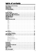
table of contents limited lifetime consumer warranty . . . . . . . . . . . . . . . . . . . . . . . . . . . . . . . . . . . . . . . . i what is included . . . . . . . . . . . . . . . . . . . . . . . . . . . . . . . . . . . . . . . . . . . . . . . . . . . . . . 3 installation tools . . . . . . . . . . . . . . . . . . . . . . . . . . . . . . . . . . . . . . . . . . . . . . . . . . . . . . 3 important information . . . . . . . . . . . . . . . . . . . . . . . . . . . . . . . . . . . . . . . . . . . . . . . . .
2 © 2006 Directed Electronics
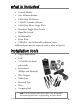
what is included ➤ Control Module ➤ One 4-Button Remote ➤ 8-Pin Main H1 Harness ➤ 7-Pin H2 Secondary Harness ➤ 6-Pin Relay Heavy Gauge Wires ➤ Shutdown Toggle Safety Switch ➤ Hood Pin Switch ➤ Installation Kit ➤ Razor Knife ➤ CDROM—Do-It-Yourself Installation Video Additional parts may be required (such as relays or bypass).
important information Congratulations on the purchase of your remote start keyless entry system. This system will allow convenient access to your vehicle with the push of a button, as well as remote start and other optional features. Properly installed, this system will provide years of trouble-free operation. Please take the time to carefully read this User’s Guide in its entirety and watch the Do-It-Yourself Installation Video (CDROM) prior to installing your system.
➜ fcc/id notice This device complies with Part 15 of FCC rules. Operation is subject to the following conditions: (1) This device may not cause harmful interference, and (2) This device must accept any interference received, including interference that may cause undesirable operation. Changes or modifications not expressly approved by the party responsible for compliance could void the user's authority to operate this device.
to assure that the system does not unintentionally remote start the vehicle. 4. THE USER MUST INSTALL A CARBON MONOXIDE DETECTOR IN OR ABOUT THE LIVING AREA ADJACENT TO THE VEHICLE. ALL DOORS LEADING FROM ADJACENT LIVING AREAS TO THE ENCLOSED OR PARTIALLY ENCLOSED VEHICLE STORAGE AREA MUST AT ALL TIMES REMAIN CLOSED. ➤ Use of this product in a manner contrary to its intended mode of operation may result in property damage, personal injury, or death.
remote start unit has not been properly installed. The remote start module must be removed or properly reinstalled so that the vehicle does not start in gear. OPERATION OF THE REMOTE START MODULE IF THE VEHICLE STARTS IN GEAR IS CONTRARY TO ITS INTENDED MODE OF OPERATION. OPERATING THE REMOTE START SYSTEM UNDER THESE CONDITIONS MAY RESULT IN PROPERTY DAMAGE OR PERSONAL INJURY. IMMEDIATELY CEASE THE USE OF THE UNIT AND REPAIR OR DISCONNECT THE INSTALLED REMOTE START MODULE.
main harness (H1), 8-pin connector H1/1 ___ BLUE H1/2 ___ VIOLET/WHITE H1/3 ___ BROWN H1/4 ___ GRAY H1/5 ___ BLACK H1/6 ___ WHITE/BLUE H1/7 ___ LT. GREEN/BLACK H1/8 ___ WHITE (-) 200mA Status Output Tachometer Input (optional) (+) Brake Switch Shutdown Input (-) Hood Pin Shutdown Input Ground (-) Remote Start Activation Input Factory Alarm Disarm/RAP Cancellation (+/- selectable) Parking Light Flash Output (optional) Use the following wiring guidelines for the H1 harness.
secondary harness (H2), 7-pin connector H2/1 ___ RED/WHITE H2/2 ___ WHITE/BLACK Lock #87A Normally Closed H2/3 ___ GREEN/BLACK Lock #30 Common Output H2/4 ___ VIOLET/BLACK Lock #87A Normally Open (Input) 15 A H2/5 ___ BROWN/BLACK UnLock #87 Normally Closed H2/6 ___ BLUE/BLACK Unlock #30 Common Output H2/7 ___ VIOLET (-) Channel 2 (auxiliary channel ie: trunk) Unlock #87A Normally Open (Input) looped back to H2/4 relay heavy gauge wires 1 ___ VIOLET (+) (30A) Output to Starter Circuit
using LED test probe note: Do not use this test probe on computerized equipment or on the tachometer wiring as damage can result. To use the LED test probe: 1. Remove the protective cover off the probe tip. Save the protective cover for reinstallation on the probe tip when the LED tester is not being used. 2. Connect the Black clip to a good chassis ground. 3. Connect the Red clip to a good +12V source. Both the Red and Green LEDs should be illuminated dimly. 4.
installation Be sure to read this section thoroughly and view the Do-ItYourself Installation CDROM video in its entirety before starting the installation. Pay special attention to all warnings to prevent personal injury or damage to your vehicle. www.designtech-intl.com) Visit our 24-hour technical Web site (w to get a vehicle-specific wiring guide prior to starting this installation. Have on hand your crash code number when contacting tech support or visiting the web site.
12 WHITE - DOOR LOCK GREEN - DOOR UNLOCK RED - IGNITION CONTROL RED/WHITE - (-) Channel 2 WHITE/BLACK - Lock #87 Normally Closed GREEN/BLACK - Lock #30 Common (Output) VIOLET/BLACK - Lock #87 Normally Open Input 15A Fused BROWN/BLACK - Lock #87A Normally Closed BLUE/BLACK - Unlock #30 Common (Output) VIOLET - Lock #87 Normally Open Input (looped to VIOLET/BLACK) H2 Heavy Gauge Wires H1 wiring quick reference guide © 2006 Directed Electronics
➜ step 1 Ground Wire The BLACK (H1/5) wire on the main 8-pin harness is ground. First strip back a ¾-inch section of the insulation off the BLACK wire and crimp a ring terminal (not provided) to that wire. Locate a clean, paint-free metal surface in the drivers kick panel. Using a self-tapping screw, drill the screw with the ring terminal to the metal area. Once screwed down, pull on the wire to ensure a good connection. note: More problems are attributed to poor ground connections than any other cause.
➜ step 2 Constant Power and Ignition wires Almost all power and ignition wires can be found behind the key cylinder under the lower drivers side dash panel. Using the appropriate hand tools, remove the lower dash panel using care not to break any parts. If the panel does not come off easily check for any additional screws you may have missed.
the kick panel area and secure it. Probe one of the thicker gauge wires. The color and identity of your specific vehicle wiring can be obtained at www.designtech-intl.com. With the key in the off position, test the suspect wire. The constant power wire will illuminate the Red LED on the test probe. warning! Before making any connection to constant battery power make sure that the two green 30 amp fuses are removed from the fuse holders on the two thick red wires (heavy gauge wires).
constant (+)12 volts. Locate the suspected wire using the www.designtech-intl.com Web site and place the red lead of the test probe on the suspected wire. With the key in the off position the probes LED will be off. Turn the key to the on position and the LED tester will illuminate Red. Now watching your probe, turn the key to the crank position. If the LED extinguishes this is not an ignition wire but an accessory wire.
+12 VDC CONSTANT (FUSED 20A) 2nd IGNITION RELAY (NOT PROVIDED) TO 2nd IGNITION 87 86 GROUND 87A 30 85 TO 2nd IGNITION +12 VDC CONSTANT (FUSED 20A) 3rd IGNITION RELAY (NOT PROVIDED) PINK/WHITE (+) OUTPUT TO 2nd IGNITION 87 86 87A 30 GROUND 85 TO 3rd IGNITION ➜ step 3 Accessory and Starter wires The starter and accessory wires will be located in the same harness as the ignition and constant power.
insulation off a small portion and solder the thick ORANGE (3) wire of the heavy gauge wire and wrap it with electrical tape. If your vehicle requires more than one accessory, an additional relay (not provided) is required. Refer to the diagram below.
wire. With the key in the off position the LED tester should be extinguished in all key positions except the crank position. In the crank position your LED tester should illuminate Red, and will extinguish when the starter disengages. note: Always check the Web site information on your vehicle for warnings regarding the starter wire and check engine lights. Some vehicles will trip a check engine light if the starter wire is cut.
+12 VDC CONSTANT (FUSED 20A) STARTER RELAY (NOT PROVIDED) 87 TO STARTER 86 GROUND 87A 30 85 TO STARTER +12 VDC CONSTANT (FUSED 20A) 2nd STARTER RELAY (NOT PROVIDED) VIOLET (+) OUTPUT TO STARTER 87 86 GROUND 87A 30 85 TO 2nd STARTER ➜ step 4 Safety Shutdown Wires warning! These wires are meant to protect the vehicle and anyone near the vehicle. They must be connected appropriately to prevent damage to the vehicle and possible bodily injury.
wire color according to the web information. With your black test probe lead still in the kick panel, probe the suspected wire with the red lead of your test probe. With the brake pedal at rest the LED tester should be extinguished. While watching the test probe, depress the brake pedal. The LED tester should illuminate Red. Once you have located the correct brake wire, solder the small BROWN (H1/3) wire of the main harness to it and wrap the connection with electrical tape.
Place the wire with the spade connector onto the pin switch and run the wire into the vehicle’s passenger compartment through a factory rubber grommet. Using a sharp, pointed object poke a hole into the grommet and attach the wire to the object with electrical tape. Pull the wire through the grommet taking extra care to keep the wire away from any moving parts or anything that will generate extreme heat.
HOOD PIN SWITCH OPEN WHEN HOOD IS CLOSED TO GRAY (H1/5) WIRE ON CONTROL MODULE HOOD PIN SWITCH CONNECTOR GRAY WIRE BYPASS TOGGLE SWITCH BLACK WIRE BYPASSED WHEN CLOSED ➜ step 5 Parking light flash There are several different types of parking light circuits. The following description is for a standard positive-triggered parking light circuit, only.
important! If the WEB vehicle information requires using resistors for parking lights, contact Directed Technical Support. Using the web information on the vehicle, locate the suspected wire and place the red lead of the test probe to a constant (+)12 volt source and secure it. Leave the black test probe lead in the kick panel,. Probe the suspected wire with the test probe. With the switch in the off position the test probe should have both LEDs illuminated dimly.
© 2006 Directed Electronics 25
➜ step 6 Door Locks The system comes with a built in relay pack for door lock operation. When attempting to interface the power door locks with your system it is important to understand that there are multiple types of door locking systems in today's vehicles. To determine your vehicle’s power door lock system, check the web information on your vehicle. If your door lock system is a different type than described in this guide, go to www.designtech-intl.
installation by locating the same wires in the vehicle’s kick panel. If no central locking switch is found, the installation may require a door lock actuator. note: Always retest the wires in the kick panel to be sure they function the same way as the wires on the switch. There are eight common types of door lock circuits (some vehicles use more unusual systems): ■ Type A: Three-wire (+) pulse controlling factory lock relays. Most GM, some Ford and Chrysler, 1995 Saturn, some new VW, newer BMW.
must have a vacuum actuator in each door. Make sure that locking the doors from the driver's or passenger side using the key activates all the actuators in the vehicle. This requires a slight modification to the door lock harness. Mercedes-Benz and Audi 1985 and newer. ■ Type F: One-wire system - cut to lock, ground to unlock. This system is found in late-model Nissan Sentras, some Nissan 240SX, and Nissan 300ZX 1992 and later. It is also found in older Mitsubishis, and some early Mazda MPV’s.
directly to the lock motors.
type B: negative-triggered, relay-driven system This system is common in many Toyota, Nissan, Honda, and Saturn models, as well as Fords with the keyless-entry system (some other Fords also use Type B). The switch will have three wires on it, and one wire will test ground all the time. One wire will pulse (-) when the switch locks the doors, and the other wire will pulse (-) when the switch unlocks the doors. This type of system is difficult to mistake for any other type.
type C: direct-wired, reversing-polarity system DOOR LOCK SWITCH (+) 12V LOCK UNLOCK X CUT X X CUT X LOCK RELAY #87 #30A H2/2 WHITE/BLACK LOCK #87A NORMALLY CLOSED H2/3 GREEN/BLACK LOCK #30 COMMON (OUTPUT) H2/4 VIOLET/BLACK LOCK #87 NORMALLY OPEN (INPUT) H2/5 BROWN/BLACK UNLOCK #87A NORMALLY CLOSED MOTOR LOCK WIRES #87A 15A #87 UNLOCK RELAY MOTOR UNLOCK WIRES #30A H2/6 BLUE/BLACK UNLOCK #30 COMMON (OUTPUT) H2/7 VIOLET UNLOCK #87 NORMALLY OPEN (INPUT) +12V CONSTANT (15A CAPABLE)
It is critical to identify the proper wires and locate the master switch to interface properly. Locate wires that show voltage when the switch is moved to the lock or unlock position. Cut one of the suspect wires and check operation of the locks from both switches. If one switch loses all operation in both directions then you have cut one of the correct wires and the switch that is entirely dead is the master switch.
■ H2/4 VIOLET/BLACK: This wire must be connected to a constant (+)12 volts. The best connection point for this wire is the constant (+)12V supply for the door lock switch*, or directly to the positive (+) battery post with a fuse at the battery post. *note: Except in GM cars with retained accessory power (RAP). In these vehicles, the (+)12V feed to the door lock switches is turned off if the doors are closed for any length of time.
type D: adding one or more after-market actuators Vehicles without factory power door locks require the installation of one actuator per door. This requires mounting the door lock actuator inside the door. Other vehicles may only require one actuator installed in the driver's door if all door locks are operated when the driver's lock is used.
type E: electrically-activated vacuum This system is found in Mercedes-Benz and Audi 1985 and newer. The door locks are controlled by an electrically activated vacuum pump. The control wire will show (+)12V when doors are unlocked and (-) ground when locked. note: The system must be programmed for 3.5-second door lock pulses, and the violet jumper between the #87 lock terminal and the #87 unlock terminal must be cut. Contact Directed technical support. See Programming section.
type F: one-wire system (cut to lock, ground to unlock) This type of door lock system usually requires a negative pulse to unlock, and cutting the wire to lock the door. (With some vehicles, these are reversed.) It is found in the late-model Nissan Sentras, some Nissan 240SX, Nissan 300ZX 1992 and later. It is also found in some Mazda MPV's. note: The violet jumper between the #87 lock terminal and the #87 unlock terminal must be cut.
type G: positive (+) multiplex This system is most commonly found in Ford, Mazda, Chrysler and GM vehicles. The door lock switch or door key cylinder may contain either one or two resistors. SINGLE-RESISTOR TYPE: If one resistor is used in the door lock switch/key cylinder, the wire will pulse (+)12V in one direction and less than (+)12V when operated in the opposite direction.
power wire, or the (+) terminal of the battery. 3. Operate the door lock switch/key cylinder in both directions to determine the resistor values. If the multimeter displays zero resistance in one direction, no resistor is needed for that direction. 4. Once the resistor value(s) is determined, refer to the wiring diagram for proper wiring.
TWO-RESISTOR TYPE: If two resistors are used in the factory door lock switch/key cylinder, the door lock switch/key cylinder will read resistance to ground in both directions. DETERMINING THE PROPER RESISTOR VALUES: To determine the resistor values, the door lock switch/key cylinder must be isolated from the factory door lock system. For testing, use a calibrated digital multimeter that is set to ohms. note: To ensure an accurate resistance reading, do not touch the resistor or leads during testing.
CHASSIS GROUND LOCK RELAY #87 #30 H2/2 WHITE/BLACK NOT USED H2/3 GREEN/BLACK LOCK #30 COMMON (OUTPUT) H2/4 VIOLET/BLACK LOCK #87A NORMALLY OPEN (INPUT) H2/5 BROWN/BLACK NOT USED #87A LOCK UNLOCK RELAY #30 #87A H2/6 BLUE/BLACK H2/7 VIOLET UNLOCK #87 NORMALLY OPEN (INPUT) VIOLET & VIOLET/BLACK ARE COMMON AT FUSE HOLDER UNLOCK #30 COMMON (OUTPUT) UNLOCK LOCK RESISTOR (IF REQUIRED) 15A #87 DOOR LOCK SWITCH/ KEY CYLINDER TO CHASSIS GROUND UNLOCK RESISTOR (IF REQUIRED) BCM ➜ step 7
On some vehicles the electrical system has too low of a voltage variance for the remote start module to see. In this case the engine will start but will only run for about ten seconds. If this is the case, it will be necessary to use the tachometer. Engine monitoring (tachometer) warning! In the following procedure do not wear loose clothing that could get entangled in rotating engine components.
Place the black lead of the multi-meter on the negative battery post and secure it. Put the multi-meter in the AC position and connect the probe to the suspect wire with the red lead of the multi-meter. Then start the vehicle with the key. With the engine at idle the multi-meter should read between .65 volts to 1.5 volts. Have a second person press the gas pedal to increase the RPMs and watch the meter display. When the RPMs increase the voltage should rise slightly.
Since most newer vehicles come equipped with a factory alarm system, it is sometimes necessary for the factory alarm to be armed/disarmed when unlocking the doors and disarmed while remote starting the vehicle. note: Some vehicles use a + trigger system. Use the www.designtech-intl.com website to determine if your vehicle has a + trigger system. If this vehicle has this system call 1-800-477-1382 for live technical assistance as special wiring and an additional relay is required.
➜ step 9 Immobilizer Bypass Modules note: Any vehicle equipped with a factory immobilizer must use an immobilizer bypass module to remote start. If not used, the vehicle ignition or fuel supply circuits could lock up and require a costly trip to the dealer to reset the computer system. Most newer vehicles have a factory engine immobilizer system designed to prevent any unauthorized use of the vehicle.
To determine what bypass module your vehicle requires, use the www.designtech-intl.com web-site in the Interface Module LookUp section. ➜ step 10 Learning the remote The system comes with one programmed transmitter. The receiver can store up to 4 different transmitter codes in memory. Additional transmitters (part no. 26131) can be ordered by contacting your local dealer at 1-800-274-0200. Use the following to add a transmitter to the system.
note: The system can only learn, after being connected and with the FIRST IGNITION ON. If not learned with the first ignition on the main power fuses will have to be disconnected from the READY REMOTE unit and then reconnected and the procedure repeated. 3. Program. Within 10-seconds, press and hold the PROG ARM button on the transmitter, until the parking lights turn off and then back on. Now release the PROG DISARM button.
➜ step 11 Testing the system Once steps 1-10 have been completed, the operation of the system can be tested. note: If power has been removed or the fuses removed, the remote(s) will have to again be learned to the system. Ensure that the two 30-amp fuses are in the relay harness RED wire fuse holders. Make sure that the vehicle is in park with the emergency brake on and the hood closed. Press once on the PROG remote to initiate the remote start function.
remote functions The receiver uses a computer-based learn routine to learn the remote buttons. ➜ standard configuration Button Press the button to lock the vehicle.
Button Press the button to unlock the vehicle. Button PROG button twice to remote start the vehicle. Press the PROG ARM PROG ARM PROG DISARM Button ARM DISARM ARM PROG Press the button DISARM ARM DISARM PROG DISARM Buttons ARMand twice to remote stop the vehicle. PROG These DISARM buttons PROG engage timer mode. Press the and ARM PROG PROG buttons simultaneously once to start the engine every 3 hours DISARM ARM (12-minute run time for 6 start cycles).
control module programming Dependent on the vehicle, use the following data with the instructions to program your system. These wire loops are found at the side of the control module. Door Lock Pulse Duration (WHITE) - Some European vehicles, such as Mercedes-Benz and Audi, require longer lock and unlock pulses to operate the vacuum pump. Programming the system to provide 3.5 second pulses will accommodate door lock interface in these vehicles. The default setting is 0.8 second door lock pulses.
Ignition Controlled Door Locks On/Off (RED) - When on, the doors will lock three seconds after the ignition is turned on and unlock when the ignition is turned off. Uncut – ignition controlled door locks on Cut – ignition controlled door locks off Diesel Mode (BLUE) - Cut this loop if you have a diesel vehicle. When cut the remote start will start the engine about 30 seconds after pressing the button once.
during normal driving. If it finds a valid tachometer signal the module will use tachometer mode, otherwise the module will use voltage mode (battery voltage will rise after the engine starts). note: If only voltage mode is desired for remote start, the Violet/White wire (H1/2) does not need to be connected. To program tachometer mode: 1. Start the engine. 2. Simultaneously press and hold the PROG and buttons ARM PROG on the transmitter within 25 seconds of starting the engine. DISARM ARM 3.
using your system ➜ warning! safety first The following safety warnings must be observed at all times: ■ When properly installed, this system can start the vehicle via a command signal from the remote. Therefore, never operate the system in an enclosed area or partially enclosed area without ventilation (such as a garage). When parking in an enclosed or partially enclosed area or when having the vehicle serviced, the remote start system must be disabled using the installed toggle switch.
must not remotely start while the car is in gear. This testing should be performed by an authorized Directed Electronics, Inc. dealer in accordance with the Safety Check outlined in the product installation guide. If the vehicle starts in gear, cease remote start operation immediately and consult with the authorized Directed Electronics, Inc.dealer to fix the problem.
➜ locking with remote To lock the doors press for one second. The doors will lock and the parking lights will flash once to confirm that the doors are locked. PROG ➜ unlocking with remote ARM To unlock the doors press DISARM for one second. The parking lights will flash twice to confirm that the doors are unlocked.
When you are ready to drive the vehicle: 1. Insert the ignition key and turn it to the ON (not the START) position. 2. Press the brake pedal. note: If the brake pedal is pressed before the key is in the ON position, the engine will shut down. While the vehicle is running during remote start operation, the system will monitor the vehicle and will automatically shut down the engine if the system receives any of the following shutdown inputs: 56 ■ The brake pedal is pressed. ■ The hood is opened.
➜ timer mode This feature allows you to remotely start and run your vehicle for 12-minutes every 3 hours (for a maximum of 6 starts for cold weather conditions). This makes it possible to warm up the engine, as well as adjust the interior temperature of the vehicle with the climate control system. If interior heating or cooling is desired, the climate controls must be preset, and the fan blower must be set to the desired level prior to remote starting the vehicle.
■ The shutdown toggle switch is put into the ON position. ■ Note: The button on the remote can be pressed twice at any time to PROG stop the engine during the 12-minute timer ARM engine run interval. The button does not affect the 3-hour DISARM PROGstarts. If the engine fails to start on time interval between engine ARM 3 attempts it is counted as one start in timer mode. The system DISARM will attempt to start again 3-hours later (if this wasn’t its 6th start attempt).
Use the following procedure to exit Pit Stop Mode: 1. Enter the vehicle. 2. Place the key into the run (not the crank or start position). 3. Step on the brake (this causes the system to exit Pit Stop Mode). trunk/auxiliary This feature allows the trunk to be opened or other accessory to be operated by the remote. Simultaneously press the and buttons.
troubleshooting ➤ The ignition comes on, but the starter will not crank. Does it start with the key in the ignition? If so, does the vehicle have an engine immobilizer? Will it start with the brake pedal depressed? (Make sure to disconnect the brake shutdown when performing this test.) If so, it may have a brake/starter interlock. Is the correct starter wire being energized? Check by energizing it yourself with a fused test lead. ➤ The starter cranks for 1 or 2-seconds but does not start.
➤ The climate control system does not work while the unit is operating the vehicle. Either the wrong accessory wire is being energized or more than one ignition or accessory wire must be energized in order to operate the climate control system. ➤ The remote start will not activate. Check to ensure that the hood is not open and that the brake pedal is not depressed. Check harnesses and connections. Make sure the harnesses are fully plugged into the remote start module.
locks" are not recommended for any high current heavy gauge wiring. Also, if the vehicle has more than one 12volt input wire, then connect one red wire to each. ➤ The vehicle starts, but immediately dies. Does the vehicle have an immobilizer? The vehicle’s immobilizer will cut the fuel and/or spark during unauthorized starting attempts. ➤ The vehicle will start and run only for about 10 seconds. Is the remote start programmed for voltage sense? Try programming the unit using a tach wire.
notes _________________________________________________ _________________________________________________ _________________________________________________ _________________________________________________ _________________________________________________ _________________________________________________ _________________________________________________ _________________________________________________ _________________________________________________ _________________________________________________ ______
64 © 2006 Directed Electronics
Cut along dotted line and fold for a quick and easy reference to keep in your purse or wallet. ✂ QUICK REFERENCE GUIDE: To lock the doors using your remote ■ Pressing for one second will lock the doors. The doors will lock and the parking lights will flash once to confirm the doors are locked. To unlock the doors using your remote ■ To unlock the doors, press for one second. The the doors will unlock and the parking lights will flash twice to confirm the doors are unlocked.
The company behind this system is Directed Electronics Since its inception, Directed Electronics has had one purpose, to provide consumers with the finest vehicle security and car stereo products and accessories available. The recipient of nearly 100 patents and Innovations Awards in the field of advanced electronic technology, DIRECTED is ISO 9001 registered. Quality Directed Electronics products are sold and serviced throughout North America and around the world.