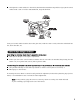
Model SR6000 installation guide ProSecurity NOTE: This product is intended for installation by a professional installer only! Any attempt to install this product by any person other than a trained professional may result in severe damage to a vehicle’s electrical system and components.
table of contents warning! safety first . . . . . . . . . . . . . . . . . . . . . . . . 4 installation points to remember . . . . . . . . . . . . . . . . 5 before beginning the installation . . . . . . . . . . . . 5 after the installation . . . . . . . . . . . . . . . . . . . . . 5 deciding on component locations . . . . . . . . . . . . . . . 6 locations for the control module . . . . . . . . . . . . . 6 locations for the siren . . . . . . . . . . . . . . . . . . . .
warning! safety first The following safety warnings must be observed at all times: ■ Due to the complexity of this system, installation of this product must only be performed by an authorized Ungo dealer. ■ When properly installed, this system can start the vehicle via a command signal from the remote control transmitter. Therefore, never operate the system in an area that does not have adequate ventilation.
installation points to remember IMPORTANT! This product is designed for fuel-injected, automatic transmission vehicles only. Installing it in a standard transmission vehicle is dangerous and is contrary to its intended use. before beginning the installation ■ Please read this entire installation guide before beginning the installation. The installation of this remote start system requires interfacing with many of the vehicle’s systems.
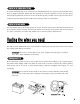
deciding on component locations locations for the siren Some things to remember about mounting the siren: ■ Keep it away from heat sources, such as radiators, exhaust manifolds, turbochargers, and heat shields. ■ Mount it where a thief cannot easily disconnect it, whether the hood is open or shut. Both the siren and its wires should be difficult to find. This usually involves disguising the wire to look like a factory harness. ■ We recommend against grounding the siren to its mounting screws.
■ The higher the control module is in the vehicle, the better the transmitter range will be. If you put the control module under a seat or inside a metal dashboard, range will diminish. Some good control module locations: above the glove box, inside the center console, above the under-dash fuse box, above the radio, etc.
locations for valet/program switch IMPORTANT! When the vehicle is delivered, please show the user where this switch is located and how to disarm the system with it. Ensure that the location you pick for the switch has sufficient clearance to the rear. The switch should be well hidden. It should be placed so passengers or stored items (such as in a glove box or center console) cannot accidentally hit it. The switch fits into a 9/32-inch hole. This system has Remote Valet.
locations for the optional starter kill relay If optional starter kill relay or its connections are immediately visible upon removal of the under-dash panel, they can easily be bypassed. Always make the relay and its connections difficult to discern from the factory wiring! Exposed yellow butt connectors do not look like factory parts, and will not fool anyone! For this reason, routing the optional starter kill wires away from the steering column is recommended.
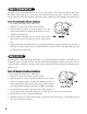
finding the 12V switched ignition wire The ignition wire is powered when the key is in the run or start position. This is because the ignition wire powers the ignition system (spark plugs, coil) as well as the fuel delivery system (fuel pump, fuel injection computer). Accessory wires lose power when the key is in the start position to make more current available to the starter motor. How to find (+)12V ignition with your multimeter: 1. Set to DCV or DC voltage (12V or 20V is fine). 2.
finding the accessory wire An accessory wire will show +12V when the key is in the accessory and run positions. It will not show +12V during the cranking cycle. There will often be more than one accessory wire in the ignition harness. The correct accessory wire will power the vehicle's climate control system. Some vehicles may have separate wires for the blower motor and the air conditioning compressor. In such cases, it will be necessary to add a relay to power the second accessory wire.
finding a (+) parking light wire The (+) parking light wire is often found near the switch. Many cars have the switch built into the turn signal lever, and in these cars the parking light wire can be found in the steering column. The same wire is often available in the kick panel or running board. NOTE: Many Toyotas, as well as many other Asian vehicles, send a (-) signal from the switch to a relay. The relay then sends (+)12V to the bulbs.
Once you have determined the wire color, the easiest place to connect to the wire is often at the kick panel, at the windshield pillar, or in the running board. When an easy location is not available, running a wire to the domelight itself is often the best solution. How to find a door pin switch trigger wire with your multimeter: 1. Set to DCV or DC voltage (12V or 20V is fine). 2. In most Fords, fasten the (-) probe of the meter to chassis ground.
primary harness (H1), 12-pin connector H1/1 H1/2 H1/3 H1/4 H1/5 H1/6 H1/7 ______ ______ ______ ______ ______ ______ ______ ORANGE WHITE WHITE/BLUE BLACK/WHITE (-) 500 mA ARMED OUTPUT (+)/(-) SELECTABLE LIGHT FLASH OUTPUT (-) REMOTE START ACTIVATION INPUT (-) 200 mA DOMELIGHT SUPERVISION OUTPUT GREEN (-) DOOR TRIGGER INPUT, ZONE 3 BLUE (-) MULTIPLEXED INPUT, ZONE 4 VIOLET (+) DOOR TRIGGER INPUT, ZONE 3 BLACK (-) CHASSIS GROUND INPUT H1/9 ______ EMPTY NOT USED H1/10 ______ BROWN H1/11 ______
door lock harness, 3-pin connector 1 ______ 2 ______ 3 ______ GREEN (-) LOCK (+) UNLOCK OUTPUT EMPTY NOT USED BLUE (+) LOCK (-) UNLOCK OUTPUT remote start ribbon harness, wiring diagram 1 ______ 2 ______ 3 ______ 4 ______ 5 ______ 6 ______ 7 ______ PINK/WHITE YELLOW PINK 200 mA (-) PROGRAMMABLE IGN2/ACC2 RELAY TURN ON (+) IGNITION INPUT TO ALARM (-) 200 mA IGNITION RELAY TURN-ON ORANGE (-) 200 mA ACCESSORY RELAY TURN-ON PURPLE (-) 200 mA STARTER RELAY TURN-ON ORANGE/BLACK BLU
heavy gauge relay satellite wiring diagram 1 2 3 4 5 6 7 8 ______ ______ ______ ______ ______ ______ ______ ______ PURPLE GREEN RED ORANGE PINK RED PINK/WHITE RED/WHITE (+) STARTER OUTPUT TO STARTER (STARTER SIDE) STARTER INPUT FROM IGNITION (KEY SIDE) (+) HIGH CURRENT 12V INPUT (+) OUTPUT TO ACCESSORY CIRCUIT (+) OUTPUT TO PRIMARY IGNITION CIRCUIT (+) (30A) HIGH CURRENT 12V INPUT (+) OUTPUT TO SECOND IGNITION CIRCUIT (+) (30A) HIGH CURRENT 12V INPUT remote start harness (H3), 5-pin connector 16 H3/1
primary harness (H1) wire connection guide H1/1 ORANGE (-) ground-when-armed output This wire supplies a (-)500 mA ground as long as the system is armed. This output ceases as soon as the system is disarmed. The orange wire may be wired to an optional starter kill relay. H1/2 WHITE (+/-) selectable light flash output As shipped, this wire should be connected to the (+) parking light wire.
H1/3 WHITE/BLUE remote start (-) activation input This input comes from the factory set to 2 activation pulses. This means that it is necessary to have 2 consecutive ground pulses on the white/blue wire for the remote start to activate or to deactivate. The same holds true for the remote control activation when set to a two pulse setting it is necessary to press the button twice for the remote start to activate or deactivate.
H1/5 GREEN (-) door trigger input, zone 3 Most vehicles use negative door trigger circuits. Connect the green wire to a wire which shows ground when any door is opened. In vehicles with factory delays on the domelight circuit, there is usually a wire that is unaffected by the delay circuitry. This wire will report Zone 3. H1/6 BLUE (-) multiplex input, zone 4 Inputs shorter than 0.8 seconds will trigger the Warn Away response, while inputs longer than 0.8 seconds will trigger the full alarm sequence.
H1/8 BLACK (-) chassis ground connection Remove any paint and connect this wire to bare metal, preferably with a factory bolt rather than your own screw. (Screws tend to either strip or loosen with time.) We recommend grounding all your components, including the siren, to the same point in the vehicle. H1/10 BROWN (+) siren output Connect this to the red wire of the siren.
IMPORTANT! Never use this wire to drive anything but a relay or a low-current input! The transistorized output can only supply 200 mA of current. Connecting directly to a solenoid, motor, or other high-current device will cause it to fail. secondary harness (H2) wire connection guide H2/1 LIGHT BLUE (-) 200mA 2nd unlock output This wire provides a second unlock output for progressive locks. Refer to document 1041—Door Locking System Wiring Guide for specific applications.
H2/4 GREEN/WHITE (-) factory alarm rearm This wire sends a negative pulse every time the remote start shuts down or the doors are locked. This can be used to pulse the arm wire of the vehicle's factory anti-theft device. Use a relay to send a (-) or (+) pulse to the arm wire. H2/5 GREY/BLACK (-) diesel wait-to-start bulb input Connect this wire to the wire in the vehicle that sends the signal to turn on the WAIT-TO-START bulb in the dashboard.
H2/6 LIGHT GREEN/BLACK (-) factory disarm This wire sends a negative pulse every time the remote start is activated or the doors are unlocked. This can be used to pulse the disarm wire of the vehicle's factory anti-theft device. Use a relay to send a (-) or (+) pulse to the disarm wire as shown in the following diagrams.
ORANGE (+) accessory output Connect this wire to the accessory wire in the vehicle which powers the climate control system. PINK (+) ignition output Connect this wire to the ignition wire in the vehicle. PINK/WHITE (+) second ignition accessory output Connect this wire to the second ignition/accessory wire in the vehicle. (See selectable menu feature 2-9.) NOTE: For vehicles that do not have a second ignition/accessory wire, this connection is not required.
remote start secondary harness (H3) wire connection guide H3/1 BLUE/WHITE (-) status output This wire supplies a 200mA output as soon as the module begins the remote start process. The H3/1 BLUE wire can also be used to activate the defogger trigger (latched/pulsed) 10-seconds after the remote start engages. (See the Feature Descriptions section in this guide for details about programming this output.) H3/2 GRAY (-) hood pinswitch input, zone 1 This wire MUST be connected to hood pinswitch.
H3/5 BLACK/WHITE neutral safety switch input Connect this wire to the provided toggle (override) switch as shown in figure A. Connect the other wire from the toggle switch to the PARK/NEUTRAL switch in the vehicle. This wire will test with ground with the gear selector either in PARK or NEUTRAL. This will prevent the vehicle from accidentally being started while in a drive gear. This input MUST rest at ground in order for the remote start system to operate.
According to available information, the only vehicles currently manufactured this way are most General Motors trucks, sport utility vehicles and column shifting passenger cars. Available information also indicates that pre1996 Dodge Dakota pickups with 2.5 liter motors are manufactured this way as well. GM vehicles that have the neutral safety switch built into the column shifter can usually be identified by a purple starter wire.
sense wire shutting down the unit prematurely. In addition, you must connect a tan (+) shut-down input to the yellow wire on the relay satellite ribbon cable. This prevents the remote start system from activating if the key is left in the "run" position. If your remote start system only has one tan input, you must use diodes to isolate the ignition circuit from the brake switch input. However, due to future manufacturer changes in vehicles, it is possible that this may not apply to all vehicles.
© 2005 Directed Electronics, Inc.
bypassing GM vehicle anti-theft systems (VATS) Vehicles with the GM VATS (Pass Key) systems have a resistor embedded in the ignition key. If the VATS decoder module does not measure the proper resistance when the vehicle is started, the starter and fuel pump may be disabled for up to ten minutes. An optional "VATS pack" of resistors is available (p/n 652T). One of the resistors in the pack will match the resistor in the key.
1995 and newer vehicle anti-theft systems (immobilizers) 1995 and newer vehicle anti-theft systems (immobilizers) require a bypass module. The bypass module allows for easy interfacing, while still maintaining the OEM system’s integrity.
ceiver will excite the transponder, which is located (but not visible) in the head of the ignition key. The key transponder will then send a unique code back to the transceiver for evaluation. If the code matches a valid code of the system, the vehicle will be allowed to start. Most of these transponder-based systems can be bypassed using p/n 555U or 556U. Some may require additional parts from the vehicle manufacturer. Consult you dealer for the applications.
shock sensor harness, 4-pin connector GREEN (-) multiplex input, zone 2 Inputs shorter than 0.8 seconds will trigger the Warn Away® response, while inputs longer than 0.8 seconds will trigger full alarm sequence and report Zone Two. If installing an optional Directed Electronics dual stage sensor, connect to the green wire as shown below. The diagram below eliminates the need for diodes to isolate the sensors.
tach learning To learn the tach signal: 1. Start the vehicle with the key. 2. Within 5 seconds, press and HOLD the Valet®/Program switch. 3. The LED will light constant when the tach signal is learned. 4. Release the Valet®/Program switch.
tach threshold on/off In most cases, this jumper can be left in the OFF position. Some new vehicles use less than 12 volts in their ignition systems. The unit may have trouble learning the tach signal in these vehicles. Changing the jumper to the ON setting changes the trigger threshold of the digital tach circuit so it will work properly with these vehicles. These vehicles include many newer Dodge/Chrysler/Plymouths, such as the Neon Cirrus/Stratus/Breeze and LH-based cars.
3. Choose. Within 10 seconds, press and release the Program switch the number of times corresponding to the desired channel listed below. Once you have selected the channel, press the switch once more and HOLD it. The LED will flash and the horn will honk (if connected) to confirm the selected channel. Do not release the Program switch.
Learn Routine will be exited if: ■ Door is closed. ■ Ignition is turned off. ■ Program switch is pressed too many times. ■ More than 15 seconds between steps. transmitter configurations The transmitters can be programmed with the standard or single button arm/disarm configurations by using the Auto Learn functions in the Transmitter/Receiver Learn Routine. standard configuration A remote that uses the standard configuration operates similarly to many factory keyless entry remotes.
and .......................operate............................Channel 4 and ......................operate............................
■ Pressing a fourth time within five seconds: The siren chirps four times followed by a long chirp. Zones Two and Four are now bypassed. ■ Pressing a fifth time within five seconds: The siren chirps five times followed by a long chirp. All input zones, except the ignition, are now bypassed. system features learn routine The System Features Learn Routine™ dictates how the unit operates. Due to the number of features, the features have been divided into three menus.
5. Transmit. The transmitter is used to select the desired setting. Pressing will change the feature to the LED ON setting (or will flash once for features with more than 2 settings). The sire will chirp once (if connected). Pressing will change the setting to the LED OFF setting (or will flash two or more times for features with more than 2 settings). 6. Release. The Valet®/Program switch can now be released.
feature menus The default settings are indicated in bold type. Features that have additional settings that can be programmed using the ProSecurity Programmer are indicated with an asterisk (*).
menu #2 - advanced features FEATURE NUMBER ONE-CHIRP SETTING (DEFAULT) TWO-CHIRP SETTING 2-1 Siren output constant Siren output pulsed 2-2 30 second siren duration* 60 second siren duration* 2-3 Nuisance Prevention Circuitry on Nuisance Prevention Circuitry OFF 2-4 Progressive door trigger Instant door trigger 2-5 Disarm from Valet, 1 pulse Disarm from Valet, 2-5 pulses 2-6 Door sensor bypass chirp on Door sensor bypass chirp OFF 2-7 Ignition controlled domelight on Ignition controll
feature descriptions The features of the system are described below. Features that have additional settings that can be selected only when programming with the ProSecurity Programmer are indicated by the following icon: menu #1 - basic features 1-1 ACTIVE/PASSIVE ARMING: When active arming is selected, the system will only arm when the transmitter is used. When set to passive, the system will arm automatically 30 seconds after the last door is closed.
1-7 DOOR LOCK PULSE DURATION: Some European vehicles, such as Mercedes-Benz and Audi, require longer lock and unlock pulses to operate the vacuum pump. Programming the system to provide 3.5 second pulses, will accommodate the door lock interface in these vehicles. The default setting is 0.8 second door lock pulses. Some modification to the door lock harness (H2) is also necessary. (See (+/-) Door Lock Outputs Harness (H4) section, "Type E - Mercedes-Benz and Audi -1985 and Newer" diagram.
2-3 NUISANCE PREVENTION CIRCUITRY™ (NPC™) ON/OFF: NPC™ stops repeated triggering of the same zone. If one zone is triggered three times in one hour, that zone is bypassed for one hour, starting from the time of the third trigger. During that hour, if the system sees a trigger on that zone again, the system resets the one hour timer. If one hour passes and the zone has not triggered again, the zone is activated and can trigger the system again.
2-10 CHANNEL 4 VALIDITY/LATCHED/LATCHED RESET WITH IGNITION/30 SECOND TIMED/90 SECOND TIMED OUTPUT: This wire provides a (-) 200mA output whenever the transmitter button(s) controlling Channel 4 is pressed. This output can be programmed to provide the following types of outputs (see also the Feature Menus section): ■ Validity: Output that will send a signal as long as the transmission is received.
3-4 PARKING LIGHTS FLASHING/CONSTANT: In the default setting, the unit will flash the vehicle's parking lights (if connected) while remote started. The constant setting will turn the parking lights on solid for the entire run duration. 3-5 CRANK TIME 0.6/0.8/1.0/1.2/1.4/1.6/1.8/2.0/4.0 SECONDS: If the unit is programmed for no engine checking or voltage sense, the crank time must be set to the appropriate duration. The default setting is 0.6 second.
nuisance prevention circuitry™ NPC™ requires that you change the way you test the system as NPC™ will bypass an input zone for 60 minutes. If the system “sees” the same zone trigger three times AND the triggers are spaced less than an hour apart, the system will bypass that input zone for 60 minutes. If that zone does not attempt to trigger the system during the 60-minute bypass period, the zone’s monitoring will begin again at the end of the hour.
timer mode By pressing the remote and buttons the parking lights will flash 4 times and then start the vehicle and run for the set duration. The remote start can be shut off by the transmitter by pressing the remote start button and remain in timer mode, but if any other shut down zones or the ignition becomes active the timer mode will cancel. 1. Press Timer mode buttons. 2. The vehicle will confirm with 4 parking light flashes. 3. A 1-second delay will start. 4.
shutdown diagnostics to perform shutdown diagnostics 1. With the ignition OFF, press and HOLD the Valet/Program button. 2. Turn the ignition ON and then back OFF while HOLDING the Valet/Program button. 3. Release the Valet/Program button. 4. Press and release the Valet/Program button. The LED will report the last shutdown for one minute or until the ignition is turned on.
3. Release the Valet®/Program switch. 4. Press and release the Valet®/Program switch within 5 seconds. The LED will flash in groups indicating the last two zones that triggered the unit for one minute or until the ignition is turned off. NOTE: The Warn Away triggers are not stored to memory and will not be reported. safety check Before vehicle reassembly, the remote system must be checked to ensure safe and trouble-free operation.
f. Activate the remote start system. ■ If the starter engages, immediately step on the brake to shut down the system. If it does engage, recheck the neutral safety input connection. The vehicle may use a mechanical neutral safety switch. (See H3/5 BLACK/WHITE neutral safety switch input in Remote Start Harness Wire Connection Guide section of this guide.) ■ If the starter does not engage, the test is complete. Once the system passes the three tests, the vehicle can be re-assembled and delivered.
■ Status LED doesn't work. You've probably guessed already, but here goes: Is it plugged in? (See Plug-In LED and Valet®/Program Switch section of this guide.) Is the LED plugged into the correct socket? ■ Door locks operate backwards. This unit has easily-reversed lock/unlock outputs. Recheck wire connections to see if you have reversed these. remote start troubleshooting ■ The remote start will not activate. 1. Check the harnesses and their connections.
2. Was the Tach Learn successful? The LED must light solid and bright to indicate a successful learn. 3. Make sure that there is a tach signal at the purple/white tach input wire of the remote start. If there is not a tach signal, recheck the connection to the vehicle’s tach wire and make sure the wire is not broken or shorted to ground leading to the remote start. ■ The vehicle will start, but will only run for 10 seconds. 1.
Shock sensor port BLACK/WHITE neutral safety input VIOLET/WHITE tachometer input BROWN (+) brake shutdown input GREY (-) hoodpin shutdown input BLUE/WHITE (-) 200mA 2nd status/defogger Transceiver Hi Lo - 563/564 Jumper tachometer threshold ProSecurity Programming data port RED/WHITE (-) 200mA channel 2 validity output RED 12V constant input BROWN (+) siren output Empty BLACK (-) ground input VIOLET (+) door trigger input BLUE (-) trunk trigger input GREEN (-) door trigger input BLACK/WHITE (-) 200mA
PURPLE starter side starter wire GREEN key side starter wire RED 12V constant input ORANGE accessory output BLUE (-) status output ORANGE (-) 200mA 2nd accessory output VIOLET (-) 200mA starter output PINK (-) 200mA 3rd ignition output These signals are from the Relay Satellite ribbon harness and are provided to drive additional optional relays.
Get Started Get Protected Ungo Pro Security 661 W. Redondo Beach Blvd. Gardena, Ca. 90247 800-GO-CLARION © 2005 Directed Electronics, Inc.