MADI.MONI User‘s Manual Version 1.
Copyright All rights reserved. Permission to reprint or electronically reproduce any document or graphic in whole or in part for any reason is expressly prohibited, unless prior written consent is obtained from the DirectOut GmbH. All trademarks and registered trademarks belong to their respective owners. It cannot be guaranteed that all product names, products, trademarks, requisitions, regulations, guidelines, specifications and norms are free from trade mark rights of third parties.
Table of contents About This Manual 5 How to Use This Manual................................................................................ 5 Conventions................................................................................................... 5 CHAPTER 1: Overview 6 Introduction.................................................................................................... 6 Feature Summary...........................................................................................
CHAPTER 5: Troubleshooting and Maintenance 35 Troubleshooting............................................................................................ 35 Maintenance................................................................................................. 35 page 4 of 40 CHAPTER 6: Technical Data 36 Index 37 MADI.MONI Manual - Version 1.
About This Manual About This Manual How to Use This Manual This manual guides you through the installation and operation of the device. Use the Table of Contents at the beginning of the manual or Index Directory at the end of the document to locate help on a particular topic. You can access more information and latest news by visiting on the DirectOut website at www.directout.eu. Conventions The following symbols are used to draw your attention to: TI P S ! indicate useful hints and shortcuts.
CHAPTER 1: Overview CHAPTER 1: Overview Introduction Welcome to MADI.MONI, DirectOut’s battery powered, mobile monitor and tester for MADI signals. MADI.MONI provides a coaxial MADI I/O for standard BNC cabling and a flexible SFP I/O to meet various connection standards by using SFP modules. Input signals are analysed (e.g. signal level, jitter, sample rate,...) and can be monitored via a headphone output.
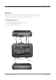
CHAPTER 1: Overview Applications MADI.MONI can be used in numerous applications where MADI connections are used. Both quick integrity check of the physical link and monitoring the audio signal serve the aim of solid operating conditions in MADI environments. Typical applications include: • ensuring stable signal connections • detection of cabling issues (poor signal condition) • line check of pre-installed cabling • portable audio signal monitoring • ...
CHAPTER 2: Legal issues & facts CHAPTER 2: Legal issues & facts Before Installing This Device WAR NING! Please read and observe all of the following NOTE!s before installing this product: • Check the hardware device for transport damage. • Any devices showing signs of mechanical damage or damage from the spillage of liquids must not be operated. • Do not use the device at extreme temperatures.
CHAPTER 2: Legal issues & facts Defective Parts/Modules WA R N I N G ! This device contains no user-serviceable parts. Therefore do not open the device. In the event of a hardware defect, please send the device to your DirectOut representative together with a detailed description of the fault. We would like to remind you to please check carefully whether the failure is caused by erroneous configuration, operation or connection before sending parts for repair.
CHAPTER 2: Legal issues & facts Updates DirectOut products are continually in development, and therefore the information in this manual may be superseded by new releases. To access the latest documentation, please visit the DirectOut website: www.directout.eu. This guide refers to firmware version 1.3. Intended Operation MADI.MONI is designed for analysis and monitoring of MADI signals (AES10).
CHAPTER 2: Legal issues & facts Conformity & Certificates CE This device complies with the basic requests of applicable EU guidelines. The appropriate procedure for approval has been carried out. RoHS (Restriction of the use of certain Hazardous Substances) This device was constructed fulfilling the directive on the restriction of the use of certain hazardous substances in electrical and electronic equipment 2002/95/EC.
CHAPTER 2: Legal issues & facts Contact Sales: DirectOut GmbH, Leipziger Str. 32, 09648 Mittweida, Germany Phone: +49 (0)3727 5665-100 // Fax: +49 (0)3727 5665-101 www.directout.eu Manufacturer: Leine-Weser-Labor GmbH, Brabeckstr. 121, 30539 Hannover, Germany Contents The contents of your MADI.MONI package should include: • 1 x MADI.MONI • 1 x USB cable • 1 x product information To complete the delivery please download from the DirectOut website: www.directout.
CHAPTER 2: Legal issues & facts Accessory Two different optical SFP modules are available from DirectOut GmbH: • Multimode SFP transceiver with LC connectors (No: DOICT0129) • Singlemode SFP transceiver with LC connectors (No: DOICT0130) Specification of the optical SFP modules: SFP Multimode Singlemode Wavelength TX 1310 nm 1310 nm Wavelenght RX 1310 nm 1310 nm Distance 2 km 10 km Powerbudget (dB) 11 dB 12 dB Protocols Fast Ethernet OC3/STM1 Gigabit Ethernet, Gigabit Fibre Channel Bandwi
CHAPTER 3: Installation CHAPTER 3: Installation Installing the Device 1. Open the packaging and check that the contents have been delivered complete and undamaged. WAR NING! Avoid damage from condensation by waiting for the device to adapt to the environmental temperature. Proper operation can only be guaranteed between temperatures of 5º C and 45º C and a maximum relative humidity of 80%, noncondensing. Ensure that the unit has sufficient air circulation for cooling. 2.
CHAPTER 3: Installation While the device is booting the currently installed firmware is indicated in the display - e.g. firmware version1.2. TI P Use the DirectOut Release Map to match your DirectOut device with the latest firmware or software release. Link: http://www.directout.eu/upload/dokumente/dotec_release_map.pdf 5. Connect an USB cable to the USB port for charging the battery or firmware updates.
CHAPTER 3: Installation 6. Installation of USB Serial driver • download the USB Serial driver • download the ‘Installation Guide for USB Control’ -- Link: http://www.directout.eu/en/support/downloads/madi-moni.html • follow the installation instructions in the ‘Installation Guide for USB Control’ T IP ! Keep any packaging in order to protect the device should it need to be dispatched for service. 7.
CHAPTER 3: Installation Charging the battery The battery ‘LEVEL’ led should be green. A yellow or red led indicates low level and requires charging the battery. To charge the battery switch off the device and and connect it to an external USB power supply or USB computer port. N OT E ! If the battery is empty the device can be operated with an external USB power supply. The battery will only be charged when the device is switched off. MADI.MONI Manual - Version 1.
CHAPTER 4: Operation CHAPTER 4: Operation Introduction This chapter describes the basic operation of the device. Note that throughout this manual, the abbreviation FS refers to sample rate or sample frequency. So, when dealing with scaling factors, the following sample rates can be written as: • 44.1 kHz or 48 kHz = 1 FS • 88.2 kHz or 96 kHz = 2 FS • 176.4 kHz or 192 kHz = 4 FS page 18 of 40 MADI.MONI Manual - Version 1.
CHAPTER 4: Operation Global Control The power switch is on the side panel. LEDs on the top panel inform about battery level or charge state. Power 1 Switch Move slider to switch device ON or OFF. USB USB 2.0 socket (Type B) Connect here for charging the battery or firmware updates. Signal Connections MADI.MONI provides two MADI I/Os: • coaxial BNC port • SFP cage to connect other media carrying MADI signals, e.g. fibre (single mode/multi mode), different wavelengths etc.
CHAPTER 4: Operation Battery The device can operate continously up to two hours with a fully charged battery. The battery level is indicated by the ‘LEVEL’ led. Battery - Charge LED (green) - indicating charge status ON = charging battery OFF = no charge flashing (1,5 Hz) = NTC fault (temperature alarm) flashing (6 Hz) = battery defective Battery - Level LED (green / yellow / red) - indicating battery level while operation green = charged (> 3.
CHAPTER 4: Operation Operating Principles The device is operated via four push buttons, ‘VOL/CH’ and ‘MENU’ navigate the parameters. The two ‘SET’ buttons (▲▼) are used for adjusting parameter values. Inputs Signal Format Signal Quality Navigation Volume Level Channel Selection Device Setting Level Meter Adjust Parameter ‘Signal Format’ and ‘Signal Quality’ inform about the signal state of the selected input.
CHAPTER 4: Operation VOL/CH Push button Push for toggling between volume control and channel selection. MENU Push button Push to enter and navigate the menu.
CHAPTER 4: Operation Display - Volume control Display The adjusted volume level is indicated. The signal can be varied within a range of -74 dBFS to 0 dBFS in steps of 2 dB. An additional boost up to 6 dB can be applied. Volume Headphone output muted. Lowest volume level for headphone output. Highest volume level for headphone output. WA R N I N G The use of headphones at high volume may harm your hearing. Display - Channel selection Display The selected channel (pair) is indicated.
CHAPTER 4: Operation Display The individual parameter of a device setting is indicated. Input Source BNC input is selected for analysis and monitoring. Monitor Mode Display - Menu settings Mono mode, monitoring of a single channel, left and right are identical. SFP input is selected for analysis and monitoring. Stereo mode, monitoring of a channel pair, odd number = left, even number = right Scaling Factor* Scaling factor for monitoring 1 (44.1 / 48 kHz) Scaling factor for monitoring 2 (88.
CHAPTER 4: Operation Output Source BNC Display The individual parameter of a device setting is indicated.
CHAPTER 4: Operation Input Selection Select between SFP I/O or coaxial BNC I/O by using the menu. SFP LED (green) - indicating selection state of SFP input OFF = SFP I/O not selected ON = SFP I/O selected BNC LED (green) - indicating selection state of BNC input OFF = BNC I/O not selected ON = BNC I/O selected Sync The device is clocked by the selected input signal.
CHAPTER 4: Operation Menu Structure Press ‚MENU‘ to enter the menu and to navigate the parameters. Use the ‚SET‘ keys to alter the setting of the parameter.
CHAPTER 4: Operation Sample Rate The sample rate (FS) of the selected input is measured and indicated by two green leds. Base rates that deviate more than 0.1 % from the standard rates 44100 Hz or 48000 Hz are indicated by individual flashing codes of both leds. Code page 28 of 40 Meaning LED Code unlock both leds OFF FS < 44056 Hz 44.1 FLASHING green 48 OFF FS = 44100 Hz ± 0.1 % 44.1 ON 48 OFF 44145 Hz < FS < 47952 Hz both leds FLASHING green FS = 48000 Hz ± 0.1 % 44.
CHAPTER 4: Operation Frame Format The frame format of the selected input is indicated by two leds. 96k Frame is available at 2 FS only while 48k Frame may be used at 1 FS, 2 FS and 4 FS. Thus a 48k Frame MADI signal needs the scaling factor to be adjusted manually for proper monitoring - see „Display - Menu settings“ on page 24. Code Meaning LED Code 48k Frame 48k ON, green 96k OFF 96k Frame 48k OFF 96k ON, yellow N OT E ! A 96k Frame signal forces the scaling factor temporarily to 2 FS.
CHAPTER 4: Operation Channel Mode The channel mode of the selected input is indicated by two green leds. Deviations from the standard’s channel counts of 56 or 64 channels (N) are indicated by individual flashing codes of both leds.
CHAPTER 4: Operation Amplitude If the BNC input is selected, the voltage of the MADI carrier is measured. Using the SFP input the module’s DDM* signalling is utilized. The analysis results are indicated by ‘traffic light’ leds.
CHAPTER 4: Operation Jitter The jitter of the MADI carrier of the selected input is analysed. The analysis results are indicated by ‘traffic light’ leds. page 32 of 40 Measured Jitter LED Code very poor LEFT FLASHING, red MID OFF RIGHT OFF poor LEFT ON, yellow MID OFF RIGHT OFF average LEFT OFF MID ON, yellow RIGHT OFF better Code good LEFT OFF MID ON, green RIGHT ON, green excellent LEFT OFF MID OFF RIGHT ON, green MADI.MONI Manual - Version 1.
CHAPTER 4: Operation Calibration BNC I/O The input of the coaxial BNC port shall be calibrated at periodic intervals to assure accuracy of the measuring. Procedure: • Connect a loop from BNC input to BNC output • Press and hold VOL/CH and MENU buttons for 5 seconds until ‘C1’ is displayed. During the calibration process ‘C2’, ‘C3’ and ‘C4’ will be displayed. When the calibration is done the device returns to normal operation mode.
CHAPTER 4: Operation This page is left blank intentionally. page 34 of 40 MADI.MONI Manual - Version 1.
CHAPTER 5: Troubleshooting and Maintenance CHAPTER 5: Troubleshooting and Maintenance Troubleshooting To identify a possible defect with the device please consult the following table. If the fault cannot be resolved using these instructions, please contact your local DirectOut representative or visit support.directout.eu. Issue Possible reason Solution Device doesn’t work. Battery discharged.
CHAPTER 6: Technical Data CHAPTER 6: Technical Data Dimensions • Width: 120 mm • Height: 90 mm • Depth: 28 mm • Weight: about 200 g Battery • Nominal Capacity: 1100 mAh (typical) • Nominal Voltage: 3.7 V • Charging via USB connection (max. 5 V) • Charging Current max. 500 mA Environmental Conditions • Operating temperature +5°C up to +45°C • Relative humidity: 10% - 80%, non condensing MADI Port BNC coaxial • 2 x BNC socket (input / output) • Impedance: 75 Ω • 0.3 V up to 0.
Index Index A Accessory................................................. 13 Amplitude................................................. 31 B Battery Charging............................................... 17 LED codes............................................ 20 Safety Instructions.................................. 8 C Calibration BNC I/O................................... 33 Channel Mode.......................................... 30 Conformity & Certificates CE..............................................
NOTE page 38 of 40 MADI.MONI Manual - Version 1.
NOTE MADI.MONI Manual - Version 1.
DirectOut GmbH Leipziger Strasse 32 09648 Mittweida Germany T: +49-3727-5665-100 F: +49-3727-5665-101 www.directout.