SNOW THROWER MODELS # 103879 & 103880 Operation Manual ! This safety alert symbol identifies important safety messages in this manual. Failure to follow this important safety information may result in serious injury or death.
For Service or Questions Call 1-877-487-8275 720-287-5182 www.dirtyhandtools.
Table of Contents Important Safety Information ......................................................4 Unpacking and Setup......................................................................7 Assembly.........................................................................................8 Filling with Gasoline and Oil........................................................10 Operation Precautions...................................................................11 Operation Controls......................
Important Safety Information ! WARNING WARNING: Read and thoroughly understand all instructions and safety information before operating this Snow thrower. Failure to do so may cause serious injury or death. Do not allow anyone to operate this Snow thrower who has not read this manual. As with all power equipment, a snow thrower can be dangerous if used improperly. Do not operate this snow thrower if you have doubts or questions concerning safe operation.
Important Safety Information General Safety Failure to follow warnings, cautions, assembly and operation instructions in the Operation Manual may result in serious injury or death. ! DANGER READ THE OPERATION MANUAL BEFORE OPERATION. •D o not permit children to operate this equipment at any time. Do not permit others that have not read and understood the complete Operation Manual to operate this equipment. •D o not operate the snow thrower when under the influence of alcohol, drugs or medication.
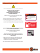
Important Safety Information Safety Decals Safety labels on the snow thrower are to remind you of important information while you are operating the unit. Make sure all safety warning decals are attached and in readable condition. Replace missing or defaced decals. Contact Dirty Hand Tools at 1-877-487-8275 for replacement decals. DANGER DANGER DANGER 101471 AVOID INJURY FROM ROTATING AUGER! KEEP HANDS, FEET AND CLOTHING AWAY! To prevent serious injury and fire: 1.
Unpacking and Setup Your snow thrower requires some assembly. Save the packing materials and box for future use as a storage container. COMPLETELY READ AND UNDERSTAND THE OPERATOR’S MANUAL BEFORE ATTEMPTING TO OPERATE THE SNOW THROWER.
Assembly NYLON LOCK NUT Handlebar and Shift Contol Assembly 1. Hex bolts and nylon lock nuts have been provided in a hardware package. Align the two holes in the handlebar connector block with the two holes in the upper and lower handlebars assemblies on the snow thrower. Push hex bolts through from the outside and secure with a nylon lock nut on the interior in two places on both sides of the snow thrower. Tighten securely (see Figure 1). 2.
Assembly DISCHARGE CHUTE FLANGE KEEPER Attaching the Discharge Chute 1. A ttach the discharge chute to the snow thrower by placing it on the chute seat on the snow thrower. Position the flange keeper beneath the chute seat lip. Align the two holes in the chute and two holes in the flange keeper and secure with two bolts from the top side (see Figure 5). Repeat in three locations to attach the discharge chute to the snow thrower. 2.
Filling with Gasoline and Oil ! WARNING FUEL IS HIGHLY FLAMMABLE AND POISONOUS ALWAYS FILL THE TANK WITH ENGINE OFF AND COOL. ALWAYS CHECK THE FUEL LEVEL BEFORE OPERATING. Allow the engine to cool for at least two minutes before removing the fuel cap. 1. Place the snow thrower on a level surface outdoors to fuel. 2. The fuel tank holds approximately 1.1 gallons of fuel. 87+ octane unleaded gasoline is recommended. Do not fill above the top of the fuel filter.
Operation Precautions ! DANGER COMPLETELY READ AND UNDERSTAND THIS MANUAL BEFORE ATTEMPTING TO OPERATE THE SNOW THROWER 1. K eep all safety guards in place and in proper working order at all times. 2. N EVER place fingers, hands, or body near the snow thrower when it is running. Do not lean or reach over the snow thrower when the machine is running. ! DANGER STOP THE ENGINE TO UNCLOG THE DISCHARGE CHUTE. NEVER USE YOUR HAND TO CLEAN OUT THE DISCHARGE CHUTE OR AUGERS. 3.
Operation Precautions ! CAUTION DISENGAGE ALL CONTROL LEVERS AND STOP THE ENGINE BEFORE YOU LEAVE THE OPERATING POSITION. Wait until the auger/impeller comes to a complete stop before unclogging the chute assembly, making any adjustments, or inspections. 1. Exercise caution to avoid slipping or falling, especially when operating in reverse. 2. Thoroughly inspect the area where the equipment is to be used. Remove all foreign objects, which could be tripped over or thrown by the auger/impeller. 3.
Operation Control AUGER CONTROL LEVER SHIFT LEVER CHUTE TILT CONTROL DRIVE CONTROL LEVER CHUTE DIRECTION CONTROL Figure 8 FORWARD CHUTE TILT 6 5 4 3 2 1 R1 R2 REVERSE HEAT There are six forward speeds and two reverse speeds. Release the drive control lever when changing speeds or direction. 103895 Shift Lever The shift lever controls the direction of travel and ground speed. There are six forward speeds. Position one (1) is the slowest and position six (6) is the fastest.
Operation ! CAUTION PRIMER BUTTON IGNITION KEY CHOKE THROTTLE FILL WITH OIL BEFORE STARTING Make sure the auger control and drive control are in the disengaged (released) position. Recoil Starter 1. To start a cold engine, move the choke to the CHOKE position (to the left). To restart a warm engine, leave the Choke in the RUN position (to the right). (See Figure 9). 2. Push the ignition key all the way in.
Operation Engaging the Drive and Auger Controls 1. W ith the throttle control in the fast position, move shift lever into one of the six forward (F) or two reverse (R) positions. Select a speed appropriate for the snow conditions and a pace you’re comfortable with. When selecting a drive speed, use slower speeds until you are familiar with the operation of the snow thrower. 2. S queeze the auger control against the handle and the auger will turn. Release it and the augers will stop. 3.
Maintenance ! WARNING BEFORE PERFORMING ANY MAINTENANCE PROCEDURE STOP THE ENGINE, WAIT FIVE (5) MINUTES TO ALLOW ALL PARTS TO COOL. Disconnect the spark plug wire, keeping it away from the spark plug. Regular maintenance is the way to ensure the best performance and long life of your machine. Please refer to this manual and the engine manufacturer’s owner’s manual for maintenance procedures. Maintenance Checklist Maintenance Procedure Before Each Use Monthly/ 20 Hours Every 6 Mo.
Maintenance ! WARNING TO PREVENT SERIOUS INJURY FROM ACCIDENTAL STARTING TURN THE POWER SWITCH OF THE ENGINE TO ITS “OFF” POSITION. AIR CLEANER COVER Wait for the engine to cool, and remove the spark plug wire before performing any inspection, maintenance, or cleaning procedures. Changing /Cleaning the Air Filter 1. W ipe off the air cleaner cover. Loosen the knob at the bottom of the air cleaner housing (see Figure 12). 2. Remove the air cleaner filter. 3.
Maintenance ! WARNING OIL IS VERY HOT DURING OPERATION AND CAN CAUSE BURNS. WAIT FOR ENGINE TO COOL BEFORE CHANGING OIL. Wait for the engine to cool, and remove the spark plug wire before performing any inspection, maintenance, or cleaning procedures. Changing the engine oil 1. Make sure the engine is stopped and is level. 2. Close the fuel valve. 3. Place a drain pan underneath the crankcase’s drain plug. 4. Remove the drain plug and, if possible, tilt the crankcase slightly to help drain the oil out.
Maintenance LUBRICATION FRAME COVER Figure 14 Gear Shaft The gear (hex) shaft should be lubricated at least once a season or after every 20 hours of operation. 1. R emove the lower frame cover by removing the two screws which secure it (see Figure 14). 2. Apply a light coating of an all-weather multi-purpose grease to the hex shaft (see Figure 15). Wheels At least once a season, remove both wheels. Clean and coat the axles with a multipurpose automotive grease then reinstall.
Maintenance Shear Pin Replacement The auger is attached to the spiral shaft with shear pins secured with cotter pins. If the auger should strike a foreign object or ice jam, the snow thrower is designed to shear off those pins (see Figure 17). If the auger will not rotate, check if the pins have been sheared. When replacing shear pins, spray an oil lubricant into the shaft before inserting new pins.
Maintenance BELT COVER Figure 19 FRAME COVER Auger Belt Replacement 1. R emove the belt cover on the front of the engine by removing the two self-tapping screws (see Figure 19). Drain the gasoline from the snow thrower, or place a container to catch leakage from the gas cap. 2. C arefully pivot the snow thrower up and forward so that it rests on the auger housing. Remove the frame cover from the underside of the snow thrower by removing four self-tapping screws which secure it (see Figure 20). 3.
Maintenance Drive Belt Replacement 1. Remove the belt cover on the front of the engine by removing the two self-tapping screws (see Figure 19). Drain the gasoline from the snow thrower, or place a container to catch leakage from the gas cap. 2. Carefully pivot the snow thrower up and forward so that it rests on the auger housing. Remove the frame cover from the underside of the snow thrower by removing four selftapping screws which secure it (see Figure 20). 3.
Maintenance Control Wire Adjustment When the auger or drive belts are adjusted or replaced, or after a long time of use, the control wires may need to be adjusted. The control wires for the drive control and the auger control are attached to the auger lever and the drive lever on the handlebar. There is a long threaded screw attached through the connecting spring near the base of the snow thrower. The screw threads into the control wire turnbuckle which is secured by a hex nut.
Engine Troubleshooting ! WARNING BEFORE PERFORMING ANY MAINTENANCE PROCEDURE STOP THE ENGINE, WAIT FIVE (5) MINUTES TO ALLOW ALL PARTS TO COOL. Disconnect the spark plug wire, keeping it away from the spark plug. PROBLEM The engine will not start. • No fuel in tank or fuel valve closed. • Choke not in start position. • Low quality or deteriorated, old gasoline. • Dirty fuel passageways blocking fuel flow. • Carburetor needle stuck. Smell of fuel in air. • Too much fuel in chamber.
Snow Thrower Troubleshooting PROBLEM No snow through thrower’s discharge chute.
Snow Thrower Troubleshooting PROBLEM Auger does not engage. • Auger control wire is too loose. • If there is too much slack in the auger control wire, the augers will not be engaged properly. Turn off the engine. Adjust the tension of the auger control wire (see page 23). • Auger is not rotating. • Shear pin(s) are missing or broken and need to be replaced. • Auger belt is off the pulley, broken or worn. • Turn off the engine and allow to cool down for several minutes.
Storage ! WARNING DO NOT STORE SNOW THROWER WITH FUEL IN TANK INDOORS Do not store in poorly ventilated areas, or near furnace, water heater, clothes dryer or gas appliance. 1. F or short term storage wait for the engine to cool, then clean the engine with a clean cloth. 2. W hen the snow thrower is to be stored for longer than 30 days, prepare the engine for storage by emptying the fuel tank and draining all fuel lines.
Warranty & Specifications IMPORTANT NOTICE We, the manufacturer, reserve the right to change the product and/ or specifications in this manual without notification. The manual is for information usage only and the pictures and drawings depicted herein are for reference only. Warranty Repair and Service Do not return this product to the store for warranty issues or repair. Call our customer service department at 720-287-5182, 1-877-487-8275, or visit www.dirtyhandtools.