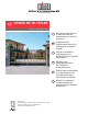
CROSS 5E-7E-7EH-8E IP1747 - rev. 2005-12-06 DITEC S.p.A. Via Mons. Banfi, 3 - 21042 Caronno Pertusella (VA) - ITALY Tel. +39 02 963911 - Fax +39 02 9650314 www.ditec.it - ditec@ditecva.com I Manuale di installazione e manutenzione per automazioni per cancelli scorrevoli. GB Installation and maintenance manual for sliding gates automatic system. F Manuel d’installation et d’entretien pour automatisme pour portails coulissants. D Montage und Wartungshandbuch für Schiebtore Automatisierung.
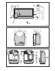
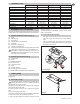
Fig. 1 Fig. 2 Cross 5E - 7E - 8E Cross 7EH Fig.
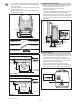
Istallazione fotocellule all’interno del motoriduttore / Installing the photocells inside the geared motor / Installation de photocellules dans le motoreducteur / Installation der photozellen im Getriebemotor / Instalacion de las fotocelulas en el interior del motorreductor. 3.5x9.5 U RX U Fig.
GB manufacture of the motorised door); draft the EC declaration of conformity in accordance with Annex II-A of the Machinery Directive and deliver it to the customer; - affix the CE marking on the power operated door in accordance with point 1.7.3 of Annex I of the Machinery Directive. For more information consult the “Technical Manual Guidelines” available on Internet at the following address: www.ditec.
1. TECHNICAL DATA Power supply Absorption Torque Condenser Max. run Door speed Max. door weight Service class Min. num. of consecutive cycles Intermittence Temperature Degree of protection Control panel 2.
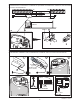
- Lay a concrete foundation with buried anchoring brackets and the base plate, making sure that it is perfectly level and smooth (see figure). Note: if the cement area is already present you can use the adjustable SUPCS base. Attention: the gearmotor must be suitably raised from the ground to avoid flooding. 3.3 Geared motor installation - Release the gearmotor and remove the key. Loosen the three frontal screws and remove the casing. Position the gearmotor onto the base plate.
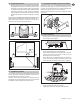
3.5 Adjusting limit switch 3.7 Cross7EHTC installation (only for Cross7EH) - Disengage the gearmotor (see OPERATING INSTRUCTIONS). Remove the pinion [14]. Fix the pinion-holding plate to the gearmotor. Fit the pinions as shown in the figure. Manually route the chain through the pinions. Fix the cover plate. Attention: with chain fitted, the gearmotor direction of rotation is reversed.
GB 4. ELECTRICAL CONNECTION 7. Electrical wiring and starting are shown in the installation manual of control panel E1-E1A (Cross5E-7E-8E) and 73RG (Cross7EH). 230 V cables (power supply, flashing light and external courtesy light, if any) are to be positioned on the right of the electric control panel, as it is shown in the figure. 24 V cables (safeties, controls and external antenna, if any) are to be positioned on the left of the electric control panel, as it is shown in the figure.
OPERATING INSTRUCTION FOR SLIDING GATES CROSS5E-7E-7EH-8E RELEASE INSTRUCTION In case of fault or power failure, insert and turn the key anticlockwise, completely open the cover. Manually open the gate. To lock the gate again, shut the cover, turn the key clockwise and remove the key. Attention: perform locking and lock release operations with motor cut off. Attention: with the cover closed and the key in a horizontal position, the lock release microswitch is open, thus preventing any operation.